
Window assembly and method for manufacturing the same

a technology for windows and doors, applied in the field of windows, can solve the problems of difficult use of tpe for concealing members, general adhesion of tpe to inorganic glass, etc., and achieve the effect of preventing unexpected damage, high degree of freedom, and not giving excessive flow resistance to the forming material

Inactive Publication Date: 2005-05-05
TOKAI KOGYO CO LTD
View PDF2 Cites 24 Cited by
  • Summary
  • Abstract
  • Description
  • Claims
  • Application Information

AI Technical Summary

Benefits of technology

[0009] According to the first aspect of the invention, it is possible to obtain the following effect. That is, a window assembly in which a base portion of a concealing member mainly formed from an olefin-based thermoplastic elastomer material or a styrene-based thermoplastic elastomer material is firmly bonded to an inorganic glass window pane can be provided.
[0023] According to a thirteenth aspect of the invention, in the manufacturing method defined in the twelfth aspect, the concealing member is bonded to the window pane while the window pane as a whole is heated to a temperature range higher than normal temperature. In this manufacturing method, since the concealing member is bonded in the condition that the outer shape of the window pane is expanded by heating, both the window pane and the concealing member are contracted by cooling after the bonding of the concealing member. For this reason, a difference in contraction amount between the window pane and the concealing member can be reduced in comparison with that in the case where the concealing member is bonded to the window pane in a temperature range not higher than normal temperature. Accordingly, according to the manufacturing method in the thirteenth aspect, in addition to the effect of the manufacturing method in the twelfth aspect, it is possible to obtain the following effect. That is, stress generated between the window pane and the concealing member is reduced to thereby avoid occurrence of failure such as distortion or deformation in the window pane and / or the concealing member more effectively.

Problems solved by technology

However, TPE has generally lower adhesion to inorganic glass than a vinyl chloride resin.
Accordingly, it is difficult to use TPE for the concealing member.

Method used


Image

  • Window assembly and method for manufacturing the same
  • Window assembly and method for manufacturing the same
  • Window assembly and method for manufacturing the same

Examples


first embodiment

[0046] The invention will be described on the case where the invention is applied to a back window of a car.

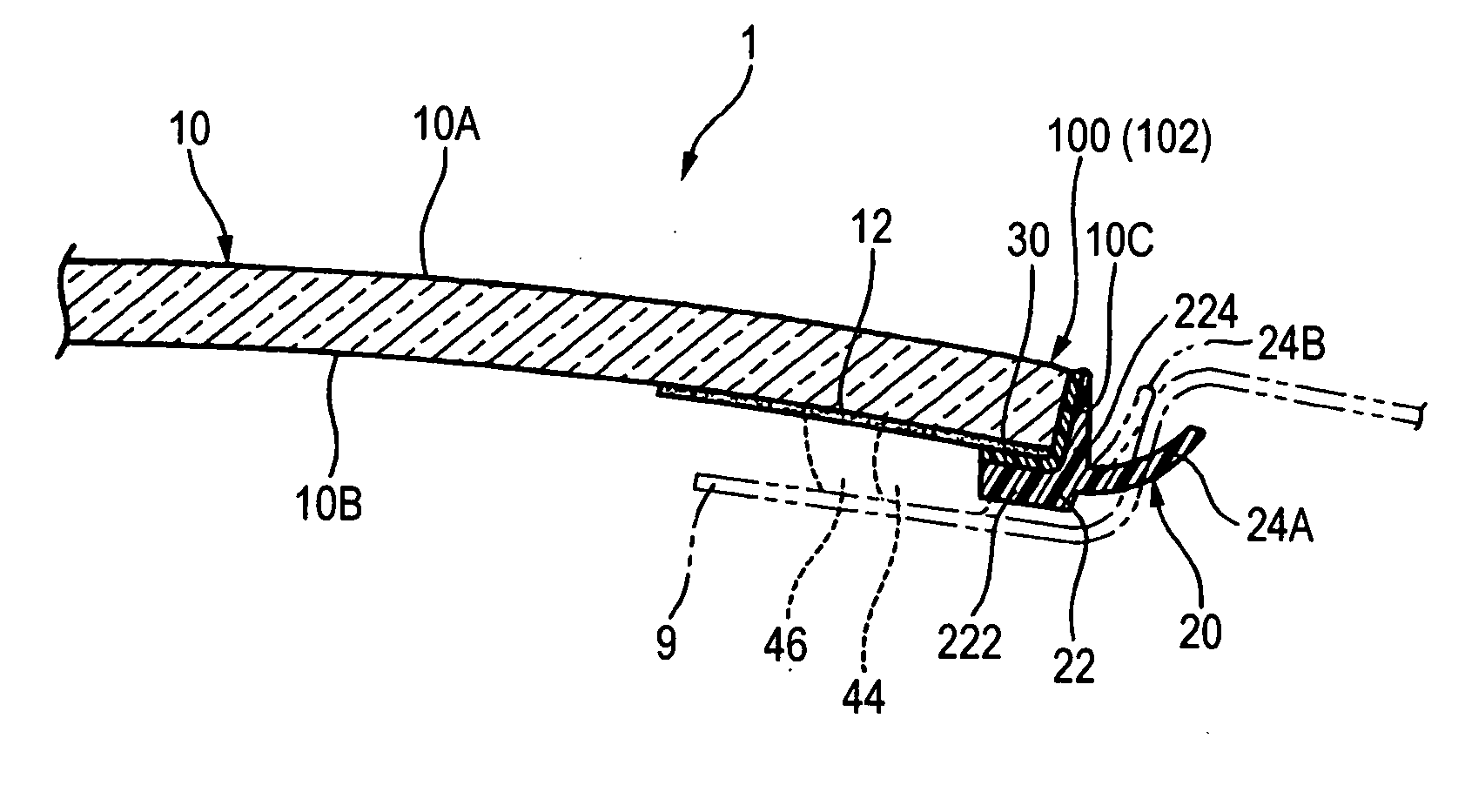
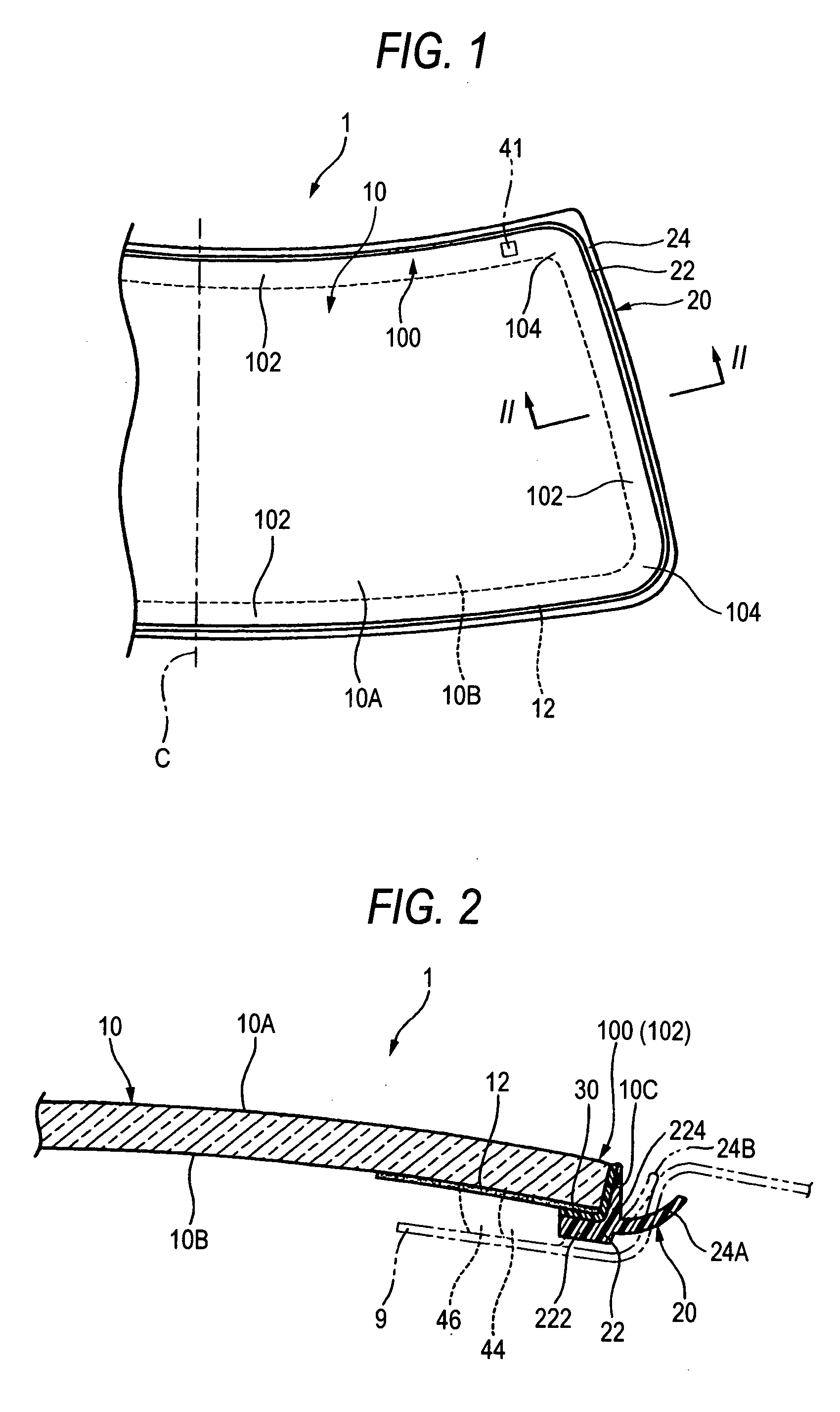
[0047] As shown in FIG. 1, a window assembly 1 for a back window according to this embodiment has a transparent window pane 10 including a front surface and a rear surface, and a concealing member 20 provided along a peripheral edge portion (peripheral edge) 100 of the transparent window pane 10. The window assembly 1 is formed to be substantially symmetrical about a line C shown in FIG. 1. The outer circumferential shape of the window pane 10 is roughly rectangular in front view. The outer circumferential shape of the window pane 10 has four linear portions 102 comparatively nearly linear and corner portions 104 located between adjacent ones of the nearly linear portions 102. In this embodiment, the concealing member 20 is formed on the whole circumference of the window pane 10. That is, the concealing member 20 is formed continuously in an area covering the linear portions ...

second embodiment

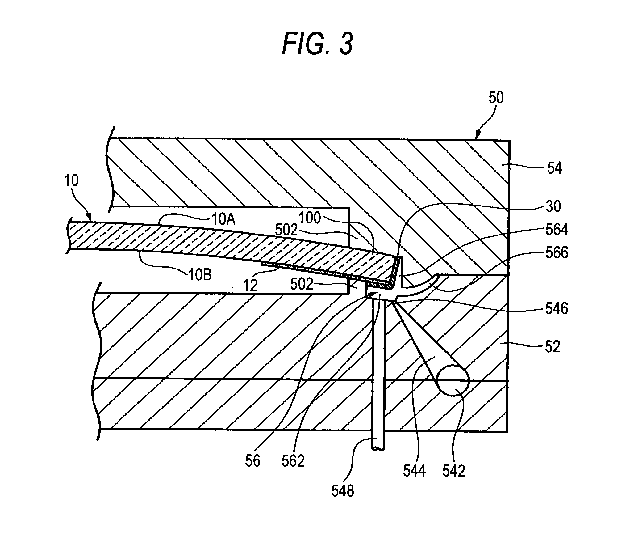
[0066] In a second embodiment, a window assembly is manufactured with a configuration in which during injection molding of a concealing member, a part of an injected material is fluidized to make it possible to bond a fixture such as an attachment clip to the rear surface of a window pane. Members having the same functions as those of the members in the first embodiment are denoted by the same reference numerals correspondingly and description of these members will be omitted.

[0067] As shown in FIG. 4, in a window pane 10, adhesive layers 30 and 32 are formed in advance on the portion of the window pane rear surface 10B where a concealing member 20 will be formed and the portion of the window pane rear surface 10B where a fixture 42 will be fixedly attached, in the same manner as in the first embodiment. When an injection mold 50 is opened, the fixture 42 is set in a predetermined position in the mold 50 (core mold part 52) and the window pane 10 is then set. When the mold 50 is cl...

third embodiment

[0069] In a third embodiment, the invention is applied to a vehicle quarter window (such as a rear quarter glass window of a passenger car or a van, or a glass window in a luggage compartment side surface of a station wagon) by way of example. As shown in FIGS. 5 and 6, in a window assembly 3 according to the embodiment, a base portion 22 of a concealing member 20 is formed continuously in an area ranging from a rear surface 10B of a peripheral edge portion 100 of a window pane 10 to a front surface 10A thereof via an end surface 10C thereof. The base portion 22 is bonded to the window pane 10 through an adhesive layer 30 provided in advance (before the concealing member 20 is formed), in the same manner as in the aforementioned embodiments. The window assembly 3 thus configured is attached so that a thin and elastic projection portion 24 of the concealing member 20 is brought into elastic contact with a car body panel constituting a window opening edge 9 of a body to be attached (a...


PUM

PropertyMeasurementUnit
temperatureaaaaaaaaaa
injection pressureaaaaaaaaaa

Abstract

A window assembly has a window pane formed from inorganic glass and a concealing member formed along a peripheral edge of the window pane. The concealing member is bonded to the window pane through an adhesive layer containing an acid-modified polyolefin resin or an acid-modified olefin-styrene copolymer resin as a main component. The concealing member is formed in such a manner that a forming material mainly containing an olefin-based thermoplastic elastomer material or a styrene-based thermoplastic elastomer material is heated and molten, and the molten forming material is brought into pressure contact with the window pane having the adhesive layer formed thereon in advance, and then cooled and solidified.

Description

BACKGROUND OF THE INVENTION [0001] 1. Field of the Invention [0002] The present invention relates to a window assembly which is in use attached to a window opening edge of a body to be attached, such as a vehicle. [0003] 2. Description of the Related Art [0004] There is a known window assembly including an inorganic glass window pane and a concealing member (also referred to as “frame”, “molding”, “gasket”, etc., which will be hereinafter generically referred to as “concealing member”) integrally and fixedly attached to the window pane along a peripheral edge of the window pane. Such a window assembly is in use attached to a window opening edge of a body to be attached such as a vehicle, a building or a work piece. The concealing member is formed from a softer material (synthetic resin, material analogous to the synthetic resin, or the like) than the window pane so as to have a function of concealing a gap between the window pane and the body to be attached. [0005] As such a window ...

Claims


Application Information

Patent Timeline
Patent Type & Authority Applications(United States)
IPC IPC(8): B29C45/14B60J1/00B60J1/02B60J1/18
CPCB29C45/14311B60J10/02B29C45/14434B60J10/70B60J10/34B60J5/0402B60R13/06C08J9/0061C08L23/0815C08L23/06
Inventor AMANO, KATSUYUKISUZUKI, AKIHIROTAKEUCHI, TOMOKI
Owner TOKAI KOGYO CO LTD
Learn More