Cartridge-type soldering iron

a soldering iron and cartridge technology, applied in the direction of ohmic resistance heating, manufacturing tools, soldering apparatus, etc., can solve the problems of obstructing precise soldering operations, rapid environmental hazards, etc., to achieve efficient and convenient work, and prevent oxidation of the soldering tip

Active Publication Date: 2005-05-05
HAKKO CO LTD
View PDF6 Cites 30 Cited by
  • Summary
  • Abstract
  • Description
  • Claims
  • Application Information

AI Technical Summary

Benefits of technology

[0009] The soldering iron described above works efficiently and conveniently even at high temperatures, while preventing oxidation of the soldering tip. Further, according to the invention, in its assembled state, a uniform gas flow path can be formed around the heating element of the cartridge-type soldering iron without creating obstacles to the use of the soldering iron in constricted spaces. The invention also makes possible a much more compact cartridge-type soldering iron, further aiding in the performance of precise soldering operations, and can perform soldering operations while emitting inert gas.

Problems solved by technology

The release of lead into the environment can lead to environmental hazards.
One of the drawbacks with lead free solder, however, is that the melting point of lead-free solder is 30° C. to 50° C. higher than the melting level of 210° C. to 232° C. of lead solder.
With such a high soldering tip temperature, flux in the solder can deteriorate, which can cause rapid oxidation in the soldering tip.
This cylindrical pipe obstructs precise soldering operations, and it is difficult to precisely position the cylindrical pipe in order to maintain a uniform flow path for the inert gas.
The supplied thread solder also hinders the soldering operation, so that it is generally not used in a printed circuit board with a high degree of concentration.
However, the plurality of projections on the outer periphery of the heating element and the inner periphery of the pipe in the '631 patent are inherently inefficient.

Method used


Image

  • Cartridge-type soldering iron
  • Cartridge-type soldering iron
  • Cartridge-type soldering iron

Examples


Embodiment Construction

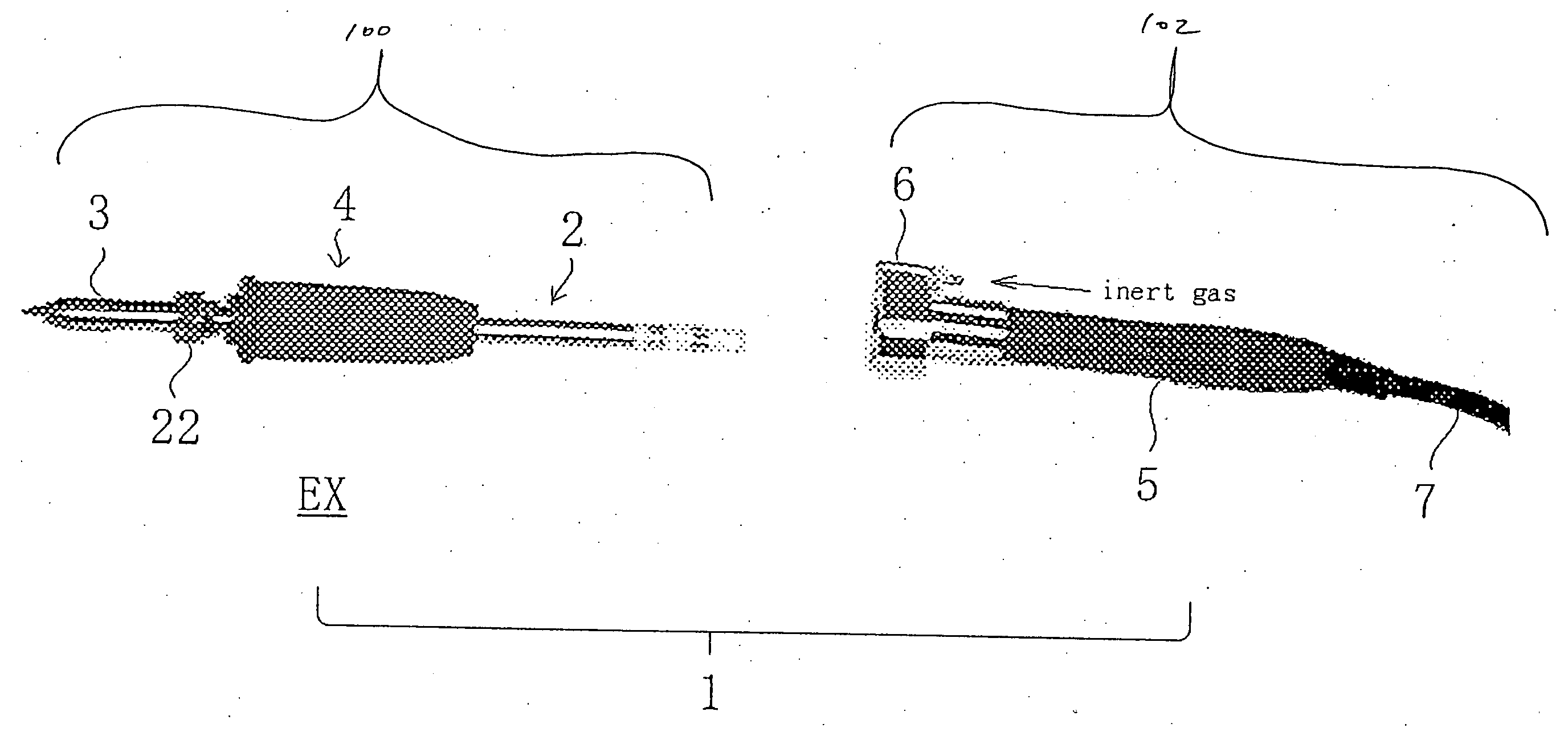
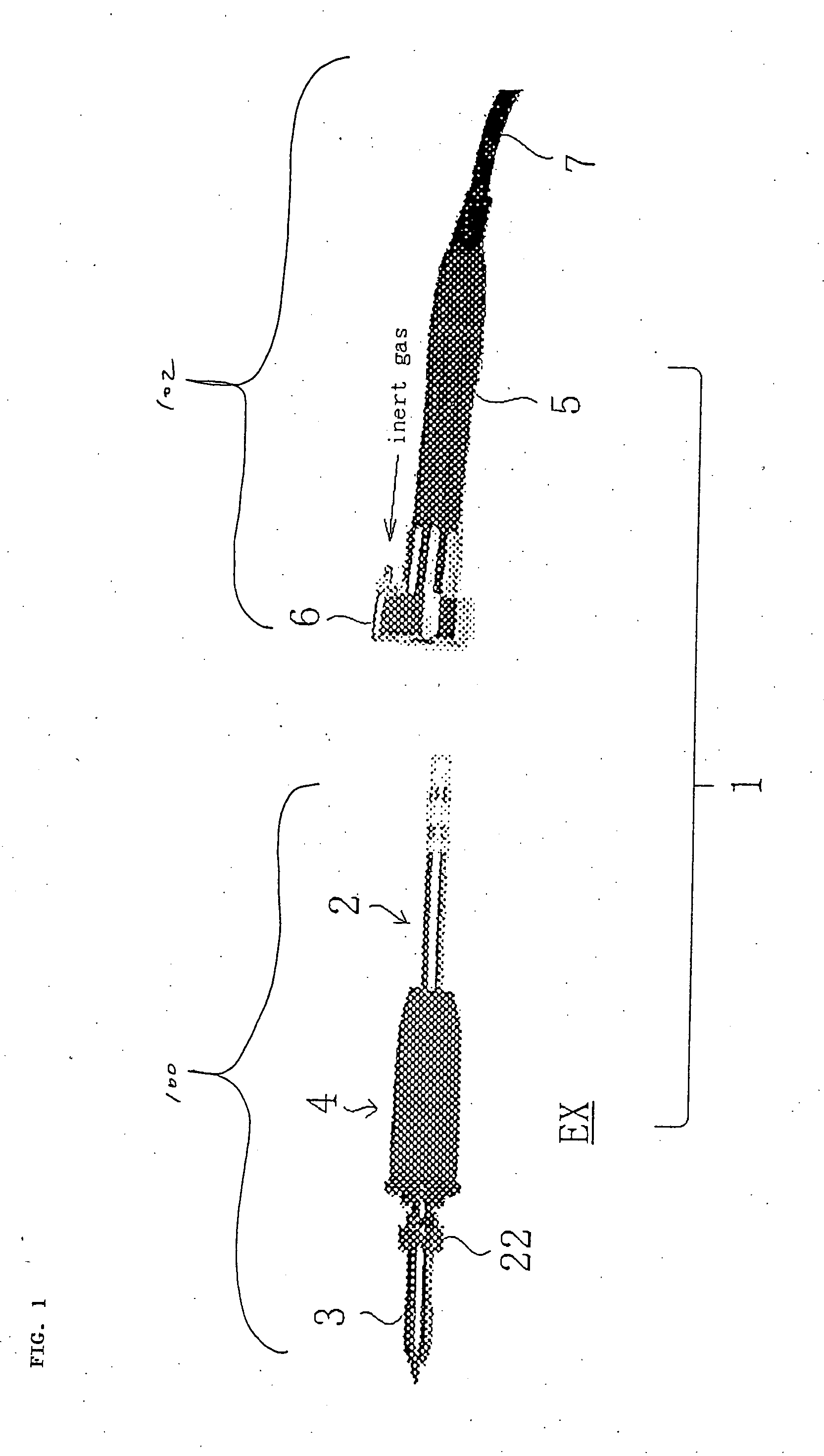
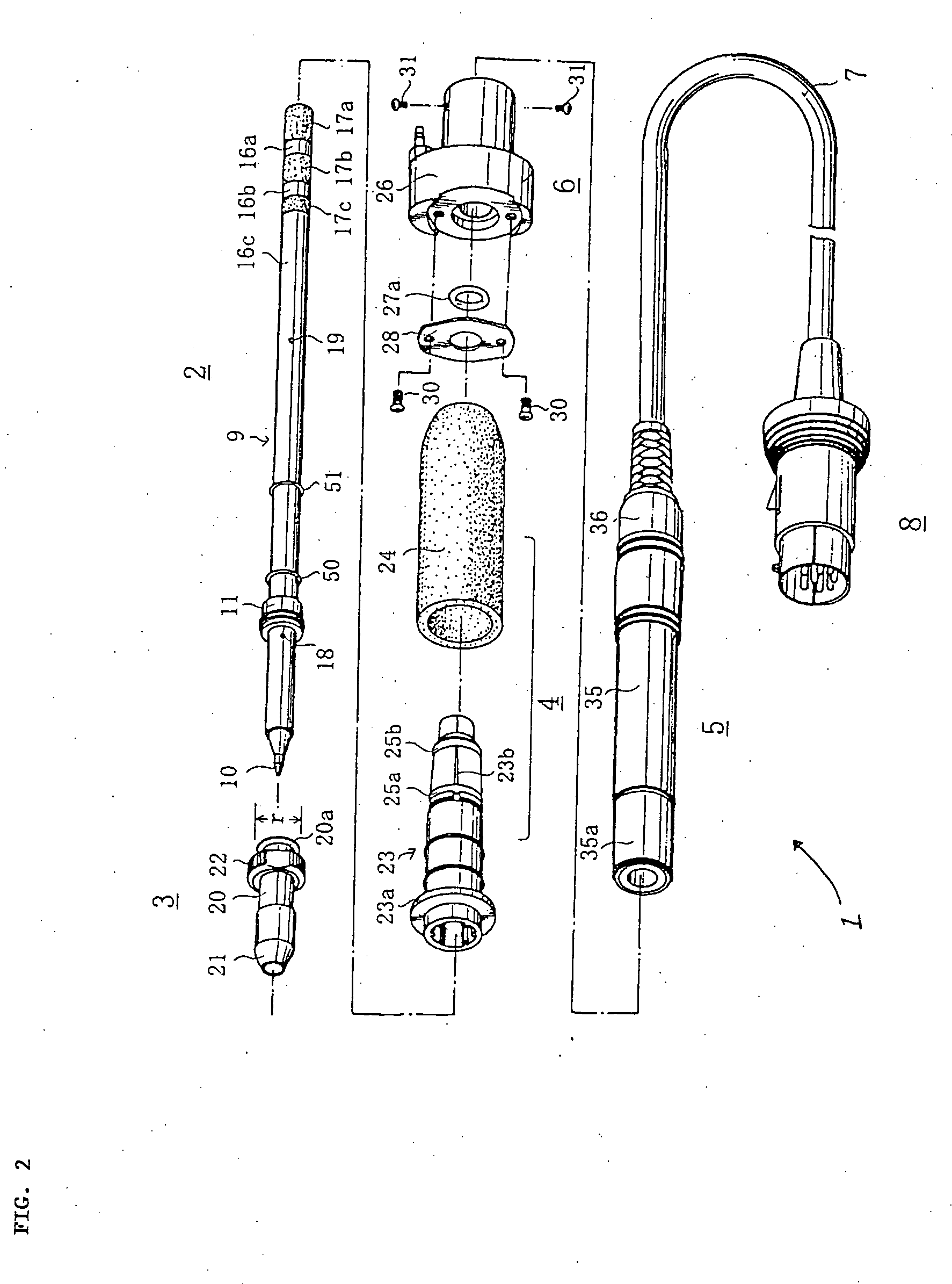
[0032]FIG. 1 illustrates a cartridge-type soldering iron (soldering iron) 1 including an exchange member 100 and a connector member 102 adapted to receive the exchange member 100. FIG. 2 is a perspective view illustrating the disassembled elements of the soldering iron 1. The exchange member 100 includes a heater cartridge 2, a gas-exhaust pipe 3 capable of coupling to a top or tip end of the heater cartridge 2, and a grip handle 4 configured to receive the heater cartridge 2. The grip handle 4 couples to the heater cartridge 2 along a central portion of the heater cartridge 2. The connector member 102 includes a handle base 5 with an inner configuration adapted to receive the base end of the heater cartridge 2 and the outer surface configured so that the top end of the handle base 5 is enclosed within a gas injector 6. The connector member 102 further includes the gas injector 6 coupled to the handle base 5 for injecting inert gas into the heater cartridge 2, and an electric connec...


PUM

PropertyMeasurementUnit
melting pointaaaaaaaaaa
temperatureaaaaaaaaaa

Abstract

A soldering iron is configured to heat its tip and emit inert gas near the tip. This is accomplished by providing a heater cartridge having a heater pipe with a tip portion and a base portion. The heater pipe has a first hole in the tip portion and a second hole at the base portion. The heater pipe has a passage between the first and second holes so that gas can enter through the second hole and exit through the first hole. The heater cartridge has a grip handle between the tip and base portions of the heater pipe. The soldering iron has a handle base with a cavity adapted to receive the base portion of the heater pipe and at least a portion of the grip handle. The handle base is adapted to provide power and gas to the base portion of the heater pipe. The heater pipe transfers the power and gas from the base portion to the tip portion to heat the tip and emit gas near the tip. The cavity of the handle base is configured to substantially seal gaps between the grip handle and the handle base so that gas does not leak between the handle base and the grip handle.

Description

RELATED APPPLICATIONS [0001] This application is a continuation-in-part of U.S. patent application Ser. No. 10 / 686,439, filed on Oct. 14, 2003, which claims priority to two Japanese patent applications, (1) 2003-101427, filed Apr. 4, 2003; and (2) 2003-118048, which was filed Apr. 23, 2003, which are all hereby incorporated by reference.BACKGROUND OF THE INVENTION [0002] 1. Field of the Invention [0003] This invention relates to a cartridge-type soldering iron capable of performing soldering operations and emitting inert gas, and more particularly, to a cartridge-type soldering iron capable of soldering operations in a constricted space. [0004] 2. General Background and State of the Art [0005] As printed circuit boards are discarded, lead (Pb) embedded in the circuit board can release into the environment. The release of lead into the environment can lead to environmental hazards. To remedy this problem, some have developed soldering compounds that are free of lead. One of the drawb...

Claims


Application Information

Patent Timeline
Patent Type & Authority Applications(United States)
IPC IPC(8): B23K1/012B23K3/03
CPCB23K1/012B23K3/0338B23K3/03
Inventor KONISHI, HIROFUMIMOCHIZUKI, TOSHIKAZU
Owner HAKKO CO LTD
Why Eureka
Try Eureka