
Printed bandpass filter for a double conversion tuner

a filter and bandpass technology, applied in the field of radio frequency signal filters, can solve the problems of inability to achieve the upper end of the television band, difficult to implement tracking filters, and inability to accurately detect the input signal, so as to reduce the need for post fabrication tuning, improve the image rejection of the input signal, and mitigate the effect of filter variation

Inactive Publication Date: 2005-05-05
AVAGO TECH WIRELESS IP SINGAPORE PTE
View PDF32 Cites 8 Cited by
  • Summary
  • Abstract
  • Description
  • Claims
  • Application Information

AI Technical Summary

Benefits of technology

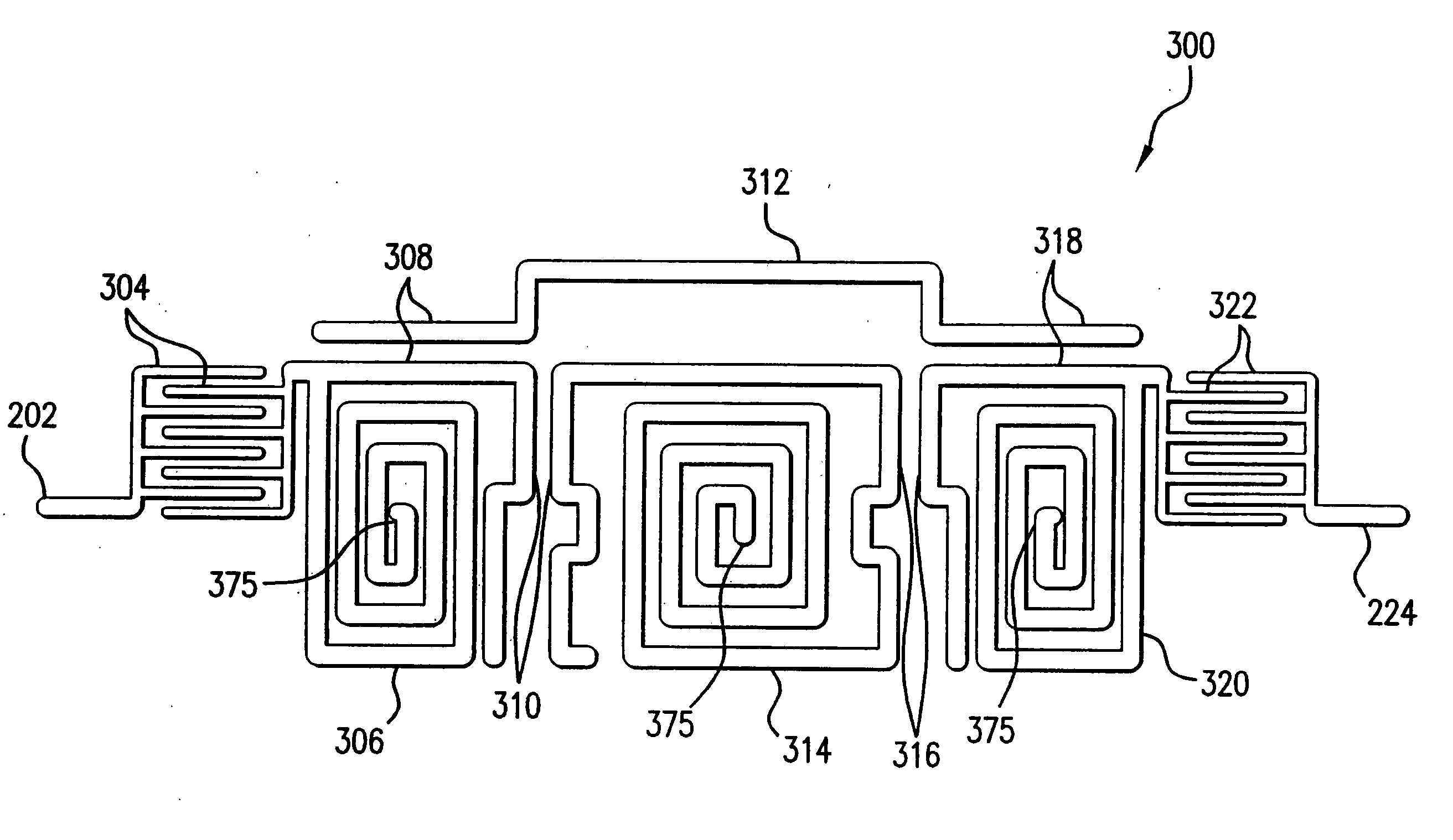
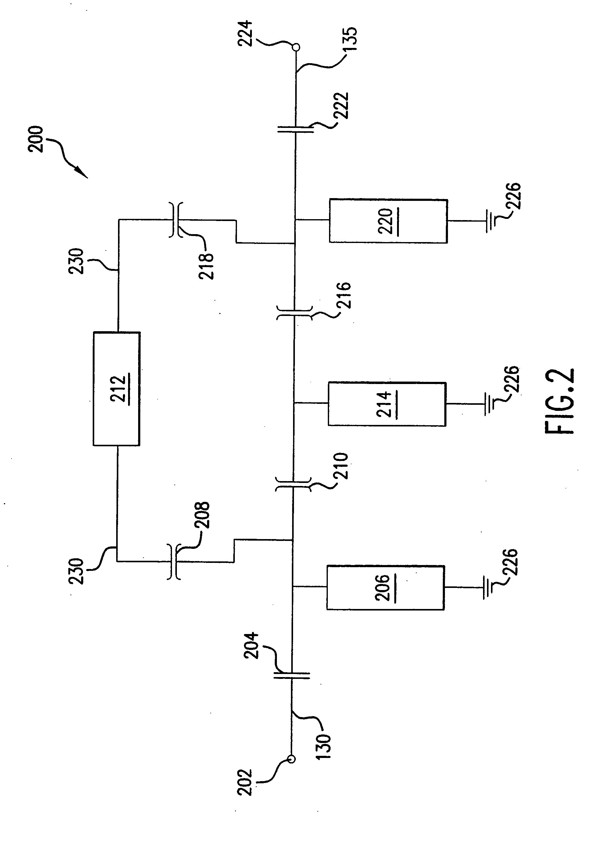
[0012] The invention is a printed bandpass filter comprising an input, a bypass line, an output, and a plurality of resonators. The input, resonators, and output are coupled to provide a desired passband. The bypass line is weakly coupled to the input and the output to improve image rejection of the input signal. The filter is printed on a precision substrate that can be mounted on a motherboard. Use of the precision substrate mitigates variations in the filter and eliminates the need for post fabrication tuning. The resonators are quarter wavelength transmission lines laid out in a pattern and coupled to ground. The resonators become open circuits at a resonant frequency.

Problems solved by technology

Tracking filters require expensive manual tuning during the assembly process.
These variations are undesirable in both analog and digital television systems.
Tracking filters are also particularly difficult to implement at the upper end of the television band, where the difference between the desired television channel frequency and the image frequency is a small fraction of the desired television frequency.
Tuning raises the cost and complexity of the filter assembly process.
However, SAW filters are relatively expensive and costly to integrate into new circuit designs, and cannot be fabricated at generic printed circuit board facilities.

Method used


Image

  • Printed bandpass filter for a double conversion tuner
  • Printed bandpass filter for a double conversion tuner
  • Printed bandpass filter for a double conversion tuner

Examples


Embodiment Construction

Example Tuner Application

[0023] Before describing the invention in detail, it is useful to describe an example tuner environment for the invention. The printed bandpass filter invention is not limited to the tuner environment that is described herein, as the bandpass filter invention is applicable to other tuner and non-tuner applications as will be understood to those skilled in the relevant arts based on the discussions given herein.

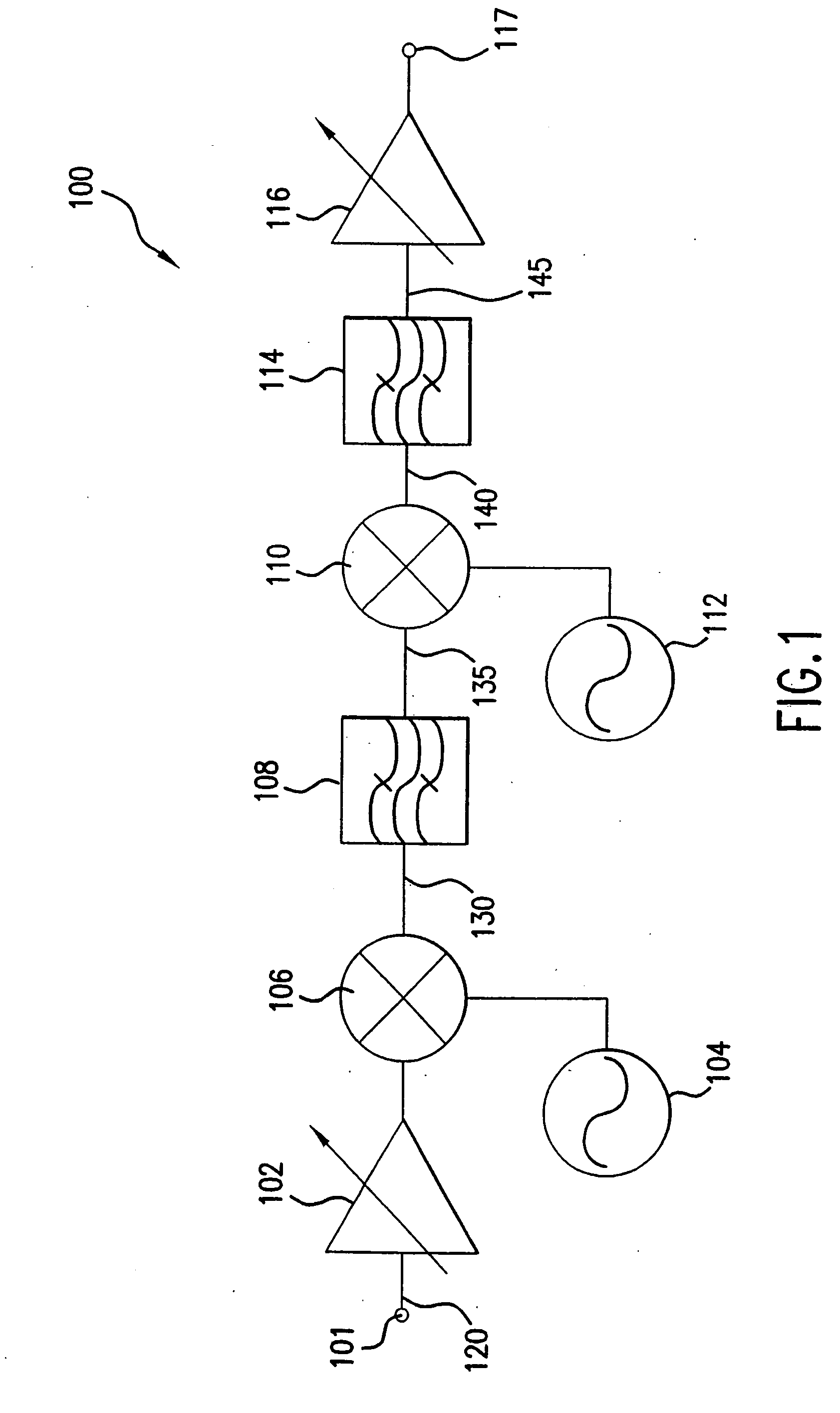
[0024]FIG. 1 illustrates a double conversion tuner 100. The double conversion tuner 100 comprises a variable gain low noise amplifier 102 coupled to a first mixer 106 and a tuner input 101. The first mixer 106 is also coupled to a first local oscillator 104. A high IF bandpass filter 108 is coupled to the first mixer 106 and a second mixer 110. The second mixer 110 is coupled to a second local oscillator 112 and a second IF bandpass filter 114. A variable gain amplifier 116 is coupled to the second IF bandpass filter 114 and the tuner output 117.

[0...


PUM


Abstract

A printed bandpass filter is mounted on a precision substrate to eliminate the need for post-fabrication tuning. The filter input is capacitively coupled to a series of quarter wavelength resonators and the filter output. The quarter wavelength resonators are printed as spirals to reduce filter size. The resonators define the bandpass characteristics of the filter. The filter also weakly couples the input signal to the filter output in a manner to cancel the signal image. Mechanical clips mitigate thermal stress on solder connections when the precision substrate is mounted on a second printed circuit board.

Description

BACKGROUND OF THE INVENTION [0001] 1. Field of the Invention [0002] The present invention relates generally to radio frequency signal filters, and more specifically to printed circuit bandpass filters. [0003] 2. Background Art [0004] Television tuners can be classified by the type of circuit used to select the desired television channel. The predominant circuit architectures in use today are single-conversion and double-conversion television tuners. [0005] Single conversion tuners usually require preselection filtering. The preselector must be a tracking bandpass filter in order to reject the image channel, which occurs at twice the intermediate frequency (IF) away from the desired television channel frequency. Tracking filters require expensive manual tuning during the assembly process. Tracking filters can have significant variations in amplitude response over the desired television channel bandwidth. These variations are undesirable in both analog and digital television systems. ...

Claims


Application Information

Patent Timeline
Patent Type & Authority Applications(United States)
IPC IPC(8): H01P1/203H05K1/16
CPCH01P1/203H05K1/165H01P1/20381H01P1/20H01P7/00
Inventor GOMEZ, RAMON A.BURNS, LAWRENCE M.CHANG, SUNG-HSIENPOBANZ, CARL W.
Owner AVAGO TECH WIRELESS IP SINGAPORE PTE
Learn More