Light-weight signal transmission lines and radio frequency antenna system

a radio frequency antenna and transmission line technology, applied in the direction of individually energised antenna arrays, collapsible antenna means, waveguides, etc., can solve the problems of increased fuel consumption, limited in certain regards, and relatively heavy antennas and associated supporting infrastructure, such as transmission lines, and achieve the effect of light weigh

a radio frequency antenna and transmission line technology, applied in the direction of individually energised antenna arrays, collapsible antenna means, waveguides, etc., can solve the problems of increased fuel consumption, limited in certain regards, and relatively heavy antennas and associated supporting infrastructure, such as transmission lines, and achieve the effect of light weigh

US20050093754A1Active Publication Date: 2005-05-05ALCATEL-LUCENT USA INC +1

Image

  • Light-weight signal transmission lines and radio frequency antenna system
  • Light-weight signal transmission lines and radio frequency antenna system
  • Light-weight signal transmission lines and radio frequency antenna system

Examples


Embodiment Construction

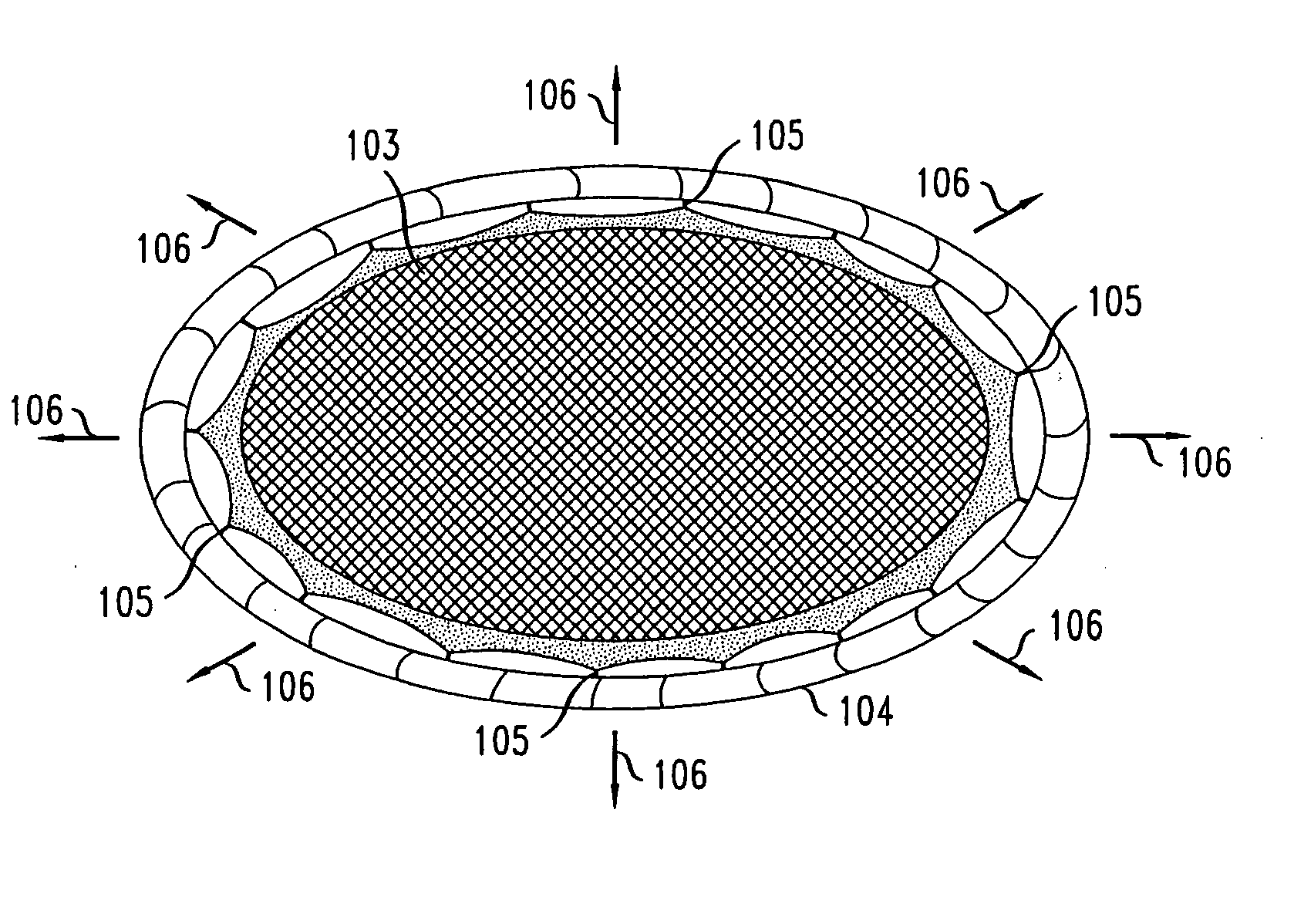
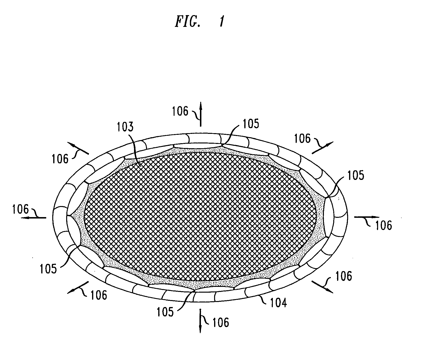
[0013]FIG. 1 shows a prior lightweight antenna structure 101 useful in RF transmission systems. In that figure, structure 101 has an antenna 102 with multiple antenna elements arranged in an array, such as is used in a phased array antenna. In certain applications, it is advantageous for the array to be substantially flat. Hence, in this prior application, the array is attached to a membrane 103 that is, in turn, connected to inflatable circular tube 104 via attachments 105. The membrane and the tube are designed such that, when tube 104 is inflated, a substantially equal amount of force is applied to membrane 103 via attachments 105. This causes membrane 103 to stretch laterally in, for example, directions 106. When the membrane 103 is sized appropriately (depending in part upon the material used for membrane 103), the resulting tension applied to membrane 103 is such that the membrane, and hence antenna array 102, becomes substantially flat.

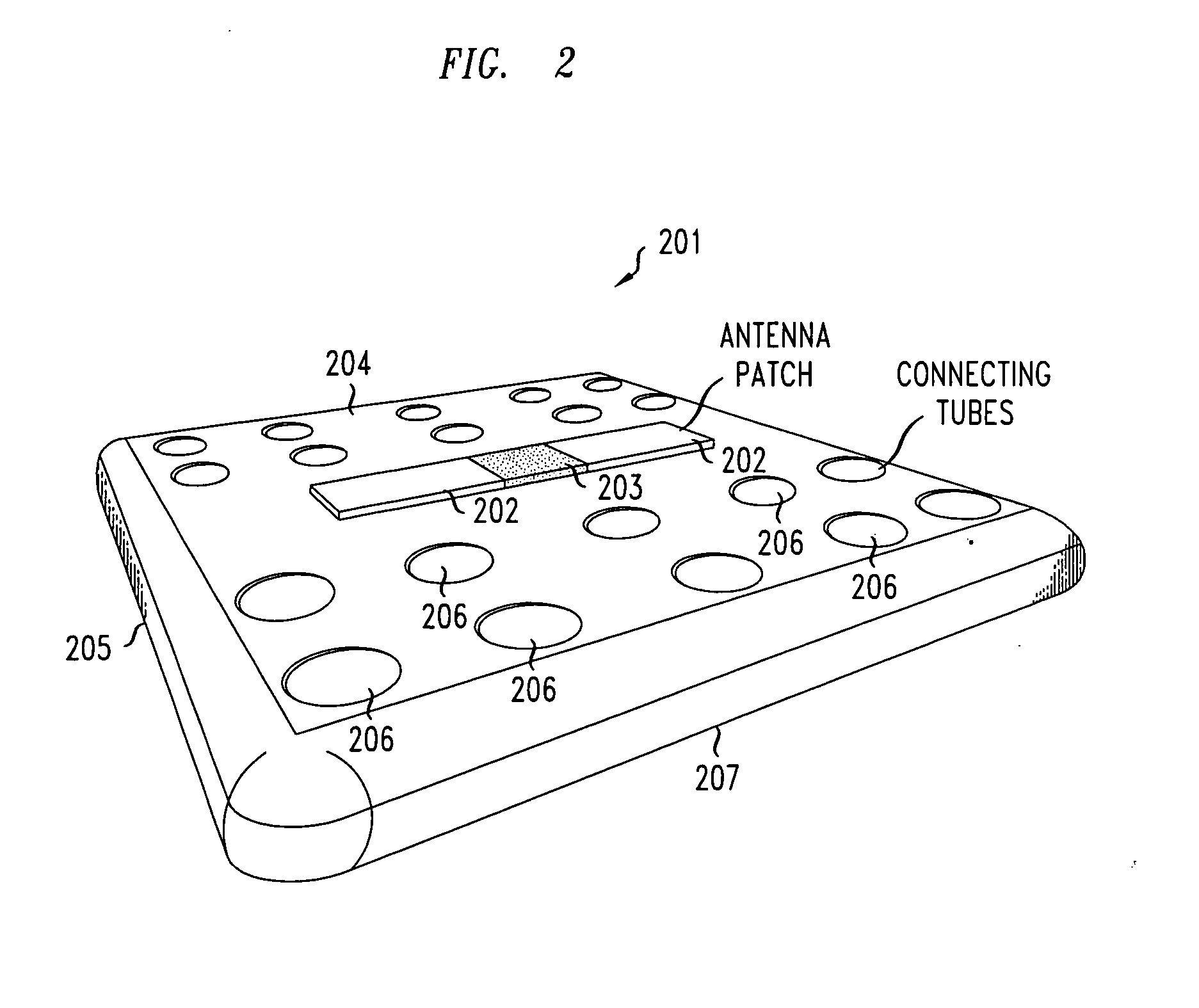
[0014]FIG. 2 shows an embodiment of a l...


PUM


Abstract

A light weight antenna system and corresponding lightweight transmission lines are disclosed that are characterized as having an extremely light weight relative to prior such systems and lines. An inflatable body having an inner surface connected to an outer surface with a plurality of support structures, such as connecting tubes. Antenna elements are disposed on the outer surface of the inflatable body to form, for example, a phased array antenna. Coaxial transmission lines are used to transmit signals to and from an antenna element and are, in one embodiment, created by disposing an inner conductor within the aforementioned connecting tubes. Such a transmission line may be utilized in a number of applications, such as to connect a base station to an antenna system of a wireless communications network. In another embodiment, quasi coaxial transmission lines are formed by disposing flexible membrane shields around a transmission elements.

Description

FIELD OF THE INVENTION [0001] The present invention relates generally to signal transmission lines and antenna systems and, more specifically, to light weight signal transmission lines and lightweight antenna systems. BACKGROUND OF THE INVENTION [0002] Light weight transmission lines and antenna systems are useful in many widely-varied applications. For example, lightweight lines and antennas may be used in an RF-based remote sensing application where objects or signals are detected or imaged from a position that may be a significant distance away from those objects or signals. In some remote sensing systems, phased-array radar systems, which are well-known in the art, have been developed to generate images of distant objects by generating a radio frequency (RF) signal and by then detecting and processing the return signal after it has “bounced” off of the distant object. [0003] Phased array radar systems are especially suited for use in remote sensing radar applications as compared...

Claims


Application Information

Patent Timeline
05 May 2005
Publication
US20050093754A1
IPC
H01P3/06; H01Q1/08; H01Q1/28; H01Q1/34; H01Q21/06
CPC
H01P3/06; H01Q21/065; H01Q1/286; H01Q1/081
Inventors
LYONS, ALAN MICHAEL; METZ, CARSTEN