Exposure method and exposure apparatus, light source unit and adjustment method of light source unit, and device manufacturing method

a technology of exposure apparatus and light source unit, which is applied in the direction of photomechanical apparatus, instruments, printing, etc., can solve the problems of reducing throughput, affecting the operation of equipment, and unable to apply the cutoff control described above, etc., and achieves the effect of reducing workload

Inactive Publication Date: 2005-05-05
NIKON CORP
View PDF22 Cites 27 Cited by
  • Summary
  • Abstract
  • Description
  • Claims
  • Application Information

AI Technical Summary

Benefits of technology

[0023] The present invention was made under such circumstances, and has as its first object to provide an adjustment method of a light source unit that makes optical axis adjustment of light emitted from a light source unit possible without fail, with little workload.

Problems solved by technology

With this type of exposure apparatus, since dose control focusing on only one point on the wafer cannot be applied, the cutoff control described above cannot be applied.
However, the repetition frequency f has limitations due to the light source performance, whereas the scanning velocity V cannot be randomly decreased since such a state will lead to a decrease in throughput.
In addition, when exposure is performed in a high sensitivity range, using a resist with high sensitivity and only a small set dose is required, as it is obvious from equation (1), if the laser beam from the pulse laser light source is used without any modification, exposure which number of pulse exceeds the minimum exposure pulse cannot be performed.
Therefore, especially in a high sensitivity range, it was sometimes difficult to set a corresponding (proportional) attenuation ratio, depending on the set dose.
Consequently, this caused a waste in pulse consumption, which increased the cost and also led to a shorter life cycle of the pulse light source and the optical system due to degradation.
Especially in a pulse light source using a laser gas such as an excimer laser, it also led to an increase in gas consumption.
In addition, when light from the light source unit enters the exposure apparatus main body with the optical axis greatly off the reference position of the exposure apparatus main body, exposure accuracy may be degraded due to uneven illuminance.
However, the longer the distance of the transmitting optical system is from the light source unit to the exposure apparatus main body, only a slight shift in position or posture of the light source unit misaligns the optical axis of the light entering the exposure apparatus main body to a large extent.
In this case, when a shift occurred in the optical axis exceeding the correctable range of the beam matching unit, a great deal of workload was necessary for optical axis adjustment, such as, in moving the entire light source unit or changing its posture.
This furthers the trend for a larger and heavier light source unit, and causes a great deal of workload for optical axis adjustment.
Furthermore, when the light source unit is moved or posture control is performed for optical axis adjustment, in many cases mechanical connection between the transmitting optical system and the light source unit has to be redone, creating a troublesome task.
In particular, when the exposure apparatus main body and the light source unit were arranged on different floors, or if there was an obstacle in between the units, the adjustment required a great deal of workload.

Method used


Image

  • Exposure method and exposure apparatus, light source unit and adjustment method of light source unit, and device manufacturing method
  • Exposure method and exposure apparatus, light source unit and adjustment method of light source unit, and device manufacturing method
  • Exposure method and exposure apparatus, light source unit and adjustment method of light source unit, and device manufacturing method

Examples


Embodiment Construction

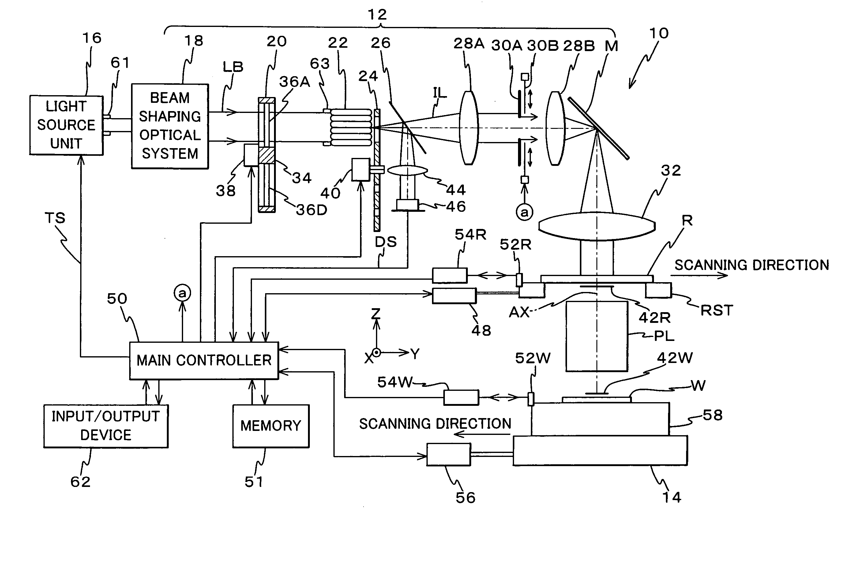
[0091] Following is a description of an embodiment related to the present invention, referring to FIGS. 1 to 7.

[0092]FIG. 1 shows an entire configuration of an exposure apparatus 10 related to the embodiment that comprises a light source unit of the present invention serving as the light source for exposure. Exposure apparatus 10 is a scanning exposure apparatus based on a step-and-scan method, that is, a so-called scanning stepper.

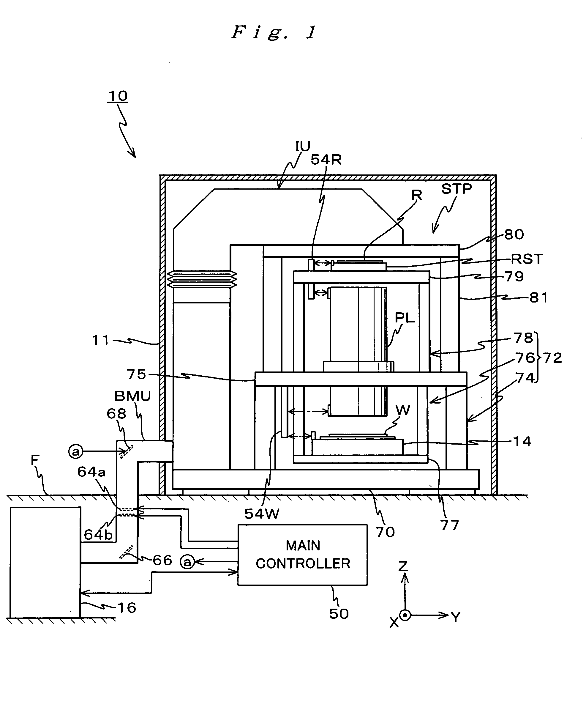
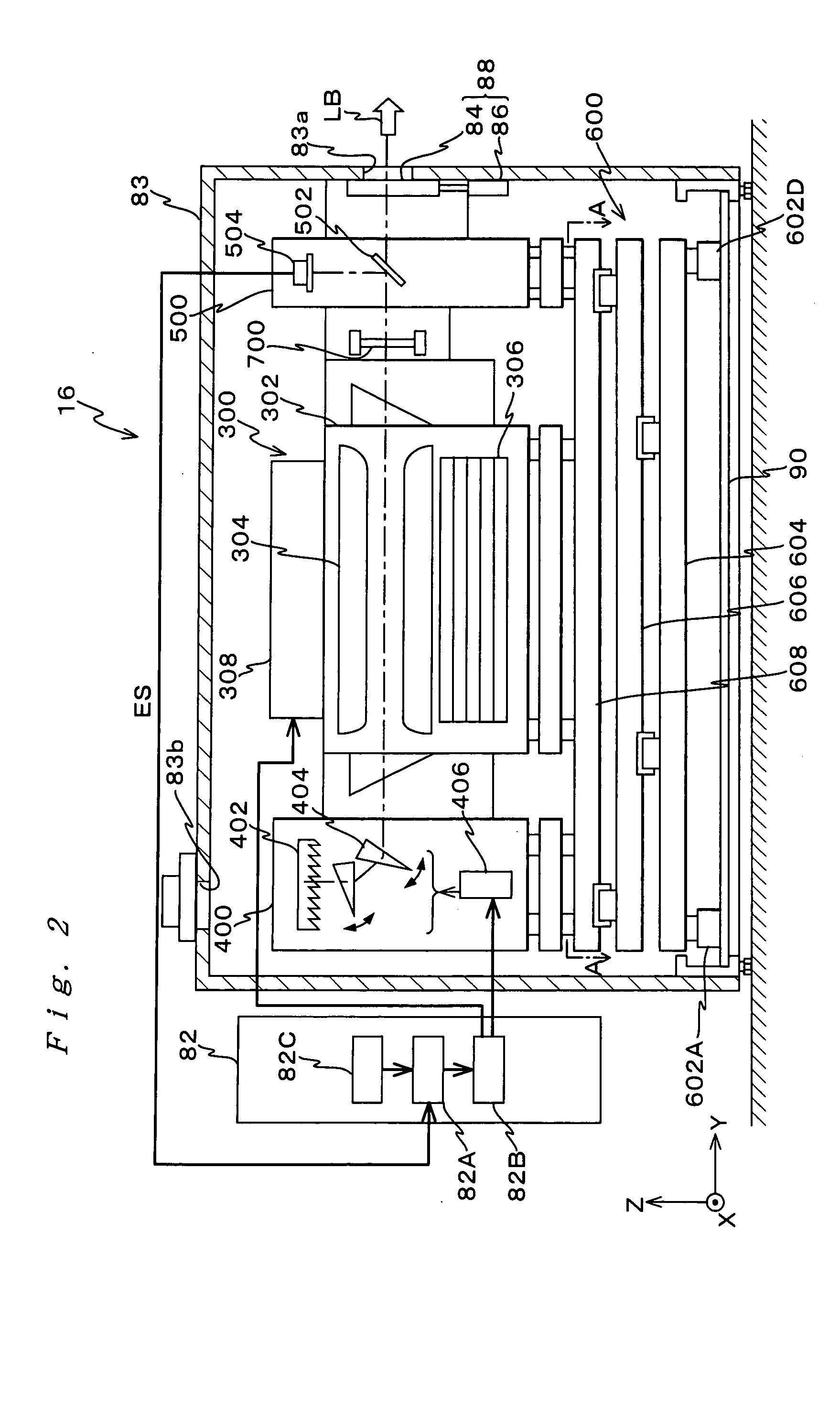
[0093] Exposure apparatus 10 comprises: an exposure apparatus main body STP arranged on a floor surface F inside a clean room in a semiconductor manufacturing factory; a chamber 11 which houses the exposure apparatus main body; a light source unit 16 arranged in a utility space provided beneath floor surface F; and a transmitting optical system that optically connects light source unit 16 and exposure apparatus main body STP, the system partially having an optical system for optical axis adjustment called a beam matching unit. In the description hereina...


PUM

PropertyMeasurementUnit
transmittanceaaaaaaaaaa
wavelengthaaaaaaaaaa

Abstract

When scanning exposure is performed by illuminating an illumination area on a mask with a pulse light from a pulse light source, synchronously moving the mask and a photosensitive object, and transferring a pattern of the mask onto the photosensitive object, a main controller performs dose control on a high sensitivity range where scanning velocity of the mask and the photosensitive object is set at a maximum so as to maintain an exposure pulse number at a minimum exposure pulse number. A pulse light source, which pulse energy is variable within a predetermined range, maintains the exposure pulse number at the minimum exposure pulse number within the variable range. The pulse light source comprises a housing in which an outgoing opening that emits a light is formed, a plurality of units housed in the housing, and a drive unit that moves the plurality of units, partially or in total inside the housing.

Description

CROSS-REFERENCE TO RELATED APPLICATIONS [0001] This application is a continuation in-part of international application PCT / JP02 / 05877, filed Jun. 13, 2002. BACKGROUND OF THE INVENTION [0002] 1. Field of the Invention [0003] The present invention relates to exposure methods and exposure apparatus, light source units and adjustment methods of light source units, and device manufacturing methods, and more particularly to an exposure method and an exposure apparatus used in a lithographic process when manufacturing devices such as a semiconductor device, a liquid crystal display device, an image pick-up device (such as a CCD), or a thin film magnetic head, a suitable light source for the exposure apparatus and its adjustment method, and a device manufacturing method using both the scanning exposure method and the scanning exposure apparatus. [0004] 2. Description of the Related Art [0005] Conventionally, when manufacturing devices such as a semiconductor device, projection exposure appa...

Claims


Application Information

Patent Timeline
Patent Type & Authority Applications(United States)
IPC IPC(8): G03F7/20
CPCG03F7/70041G03F7/70558G03F7/70358H01L21/027
Inventor HAGIWARA, SHIGERUKURITA, SHINICHI
Owner NIKON CORP
Why Eureka
Try Eureka