Polyphase power distribution and monitoring apparatus

a monitoring apparatus and polyphase technology, applied in the direction of substation/switching arrangement casings, coupling device connections, instruments, etc., can solve the problems of unbalanced load, more complex three-phase circuits, and more complex three-phase circuits, and achieve the effect of convenient manufacture, installation and us

Inactive Publication Date: 2005-05-05
SERVER TECHNOLOGY
View PDF11 Cites 40 Cited by
  • Summary
  • Abstract
  • Description
  • Claims
  • Application Information

AI Technical Summary

Benefits of technology

[0017] Preferably, each of the power information monitors is readily viewable by a user during installation or use of the apparatus. Preferably, the apparatus readily provides information and associated sensory alarms, such as audio alarms, indicative of possible load balance or imbalance between the power phases dist...

Problems solved by technology

Although three phase circuits are somewhat more complex than single or dual phase circuits, they too weigh less than single phase circuitry for the same loads supported by the circuitry.
One reason that three phase circuits are more complex than typical single phase and dual phase circuits is the need to maintain at least somewhat balanced loads among each of the three phases.
If the level of current flowing through a phase line is different than that flowing through a different phase line, the load is obviously unbalanced.
In a wye connected system, imbalance can also be indicated by current flowing through the neutral line, and this situation can arise when the amount of current flowing through each phase is identical in amplitude but differing in phase due to the nature of the loads served by the lines.
Imbalance between the loads can result in damage to the three phase system, can cause excessive wear of components in the system such as the three-phase generator, and can be difficult and costly to correct.
If the current indicated for one phase set (branch) is different than that for another current indicated for a different phase set of outputs, the loads are unbalanced.
The applicant has discovered that another problem with this type o...

Method used


Image

  • Polyphase power distribution and monitoring apparatus
  • Polyphase power distribution and monitoring apparatus
  • Polyphase power distribution and monitoring apparatus

Examples


Embodiment Construction

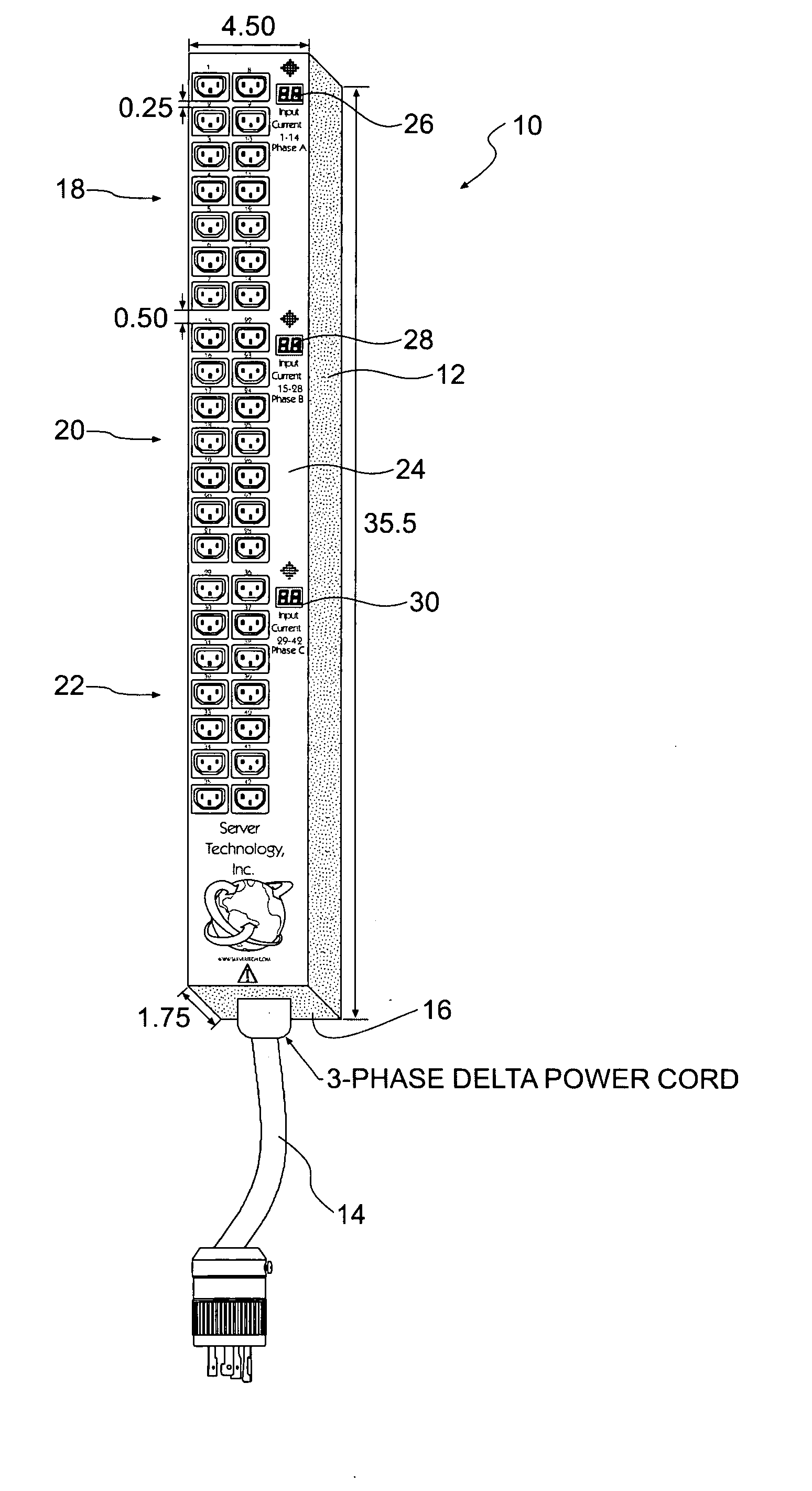
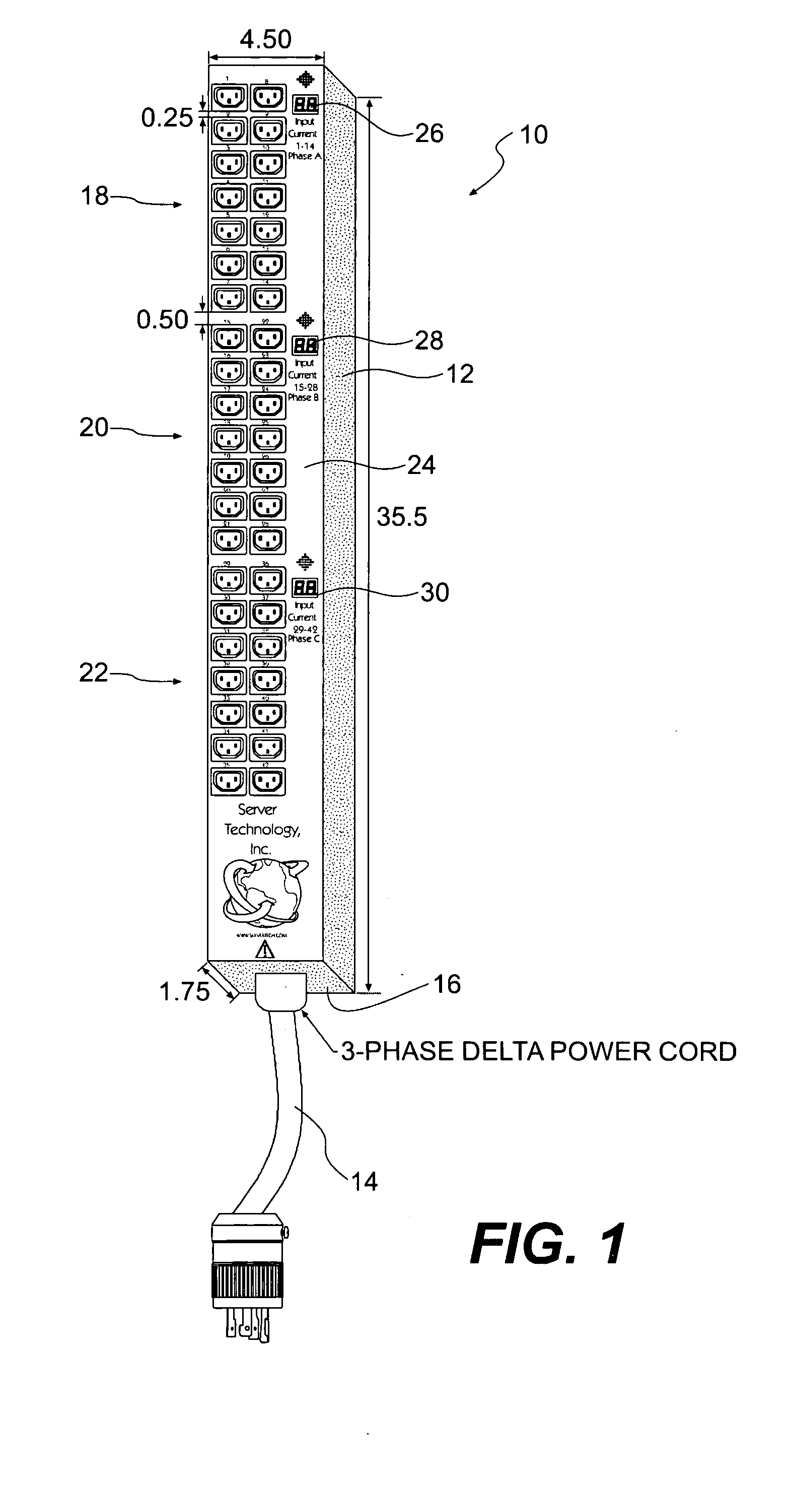
[0026] With reference to FIG. 1, the preferred three-phase delta power distribution and monitoring apparatus, generally 10, has an elongated steel housing 12, a three-phase power input cord 14 penetrating one end 16 of the housing 12, three sets of power output plug receptacles, generally 18, 20, and 22 on an elongated faceplate side 24 of the housing 12, and, adjacent each set of power output plug receptacles 18, 20, and 22, an associated phase line current display 26, 28, 30 respectively. In the preferred embodiment of FIG. 1, the housing 12 measures 35.5 inches long, by 4.5 inches wide, by 1.75 inches deep.

[0027] The entire power distribution and monitoring apparatus 10 weighs twenty-one to twenty-three lbs. depending on a length of a power cord and is easily transported and vertically mounted on an associated RETMA electronic equipment rack (not shown). In the preferred embodiment, the housing 10 can include fasteners and fastener passages (not shown) in order to secure the hou...


PUM


Abstract

A polyphase power distribution and monitoring apparatus having sets of outputs for each phase of power and monitors for each phase of power disposed in the housing. Each monitor provides a visible display of current for an associated phase of power and an audible alarm for each phase of power if the current exceeds a predetermined value or falls below a predetermined value. In three-phase wye power systems, the apparatus preferaby includes a neutral line monitor, including a neutral line current display and audio alarm, for the neutral line of the wye power circuit. The apparatus preferably is lightweight, elongated, portable, and mountable to the side of an electronic equipment rack. It may also include additional power monitoring systems such as network power monitoring tools for remotely monitoring the apparatus.

Description

FIELD OF THE INVENTION [0001] The present invention relates to power distribution apparatus for the distribution of polyphase alternating current. More particularly, the present invention relates to apparatus for distributing polyphase alternating current and monitoring information relating to polyphase power distributable by the apparatus. BACKGROUND [0002] Electric current that reverses periodically, usually many times per second, is called “alternating current.” In most public or commercial power distribution networks, electrical current is delivered to a customer or user as alternating current. [0003] Electric current is induced to reverse or alternate periodically by a voltage that reverses or alternates periodically. One complete voltage period, with accompanying current flow in one direction and then the other, is called a cycle. In the United States, 60 cycles per second (also referred to as “60 Hz”) is the standard frequency of alternating current in most environments. In E...

Claims


Application Information

Patent Timeline
IPC IPC(8): H02G3/00
CPCH02G3/00H02H3/08H01R2103/00H01R13/6691H01R25/003
Inventor CLEVELAND, ANDREW J.
Owner SERVER TECHNOLOGY
Why Eureka
Try Eureka