Master disk exposure apparatus and master disk exposure method

Inactive Publication Date: 2005-05-05
HITACHT MAXELL LTD
View PDF9 Cites 2 Cited by
  • Summary
  • Abstract
  • Description
  • Claims
  • Application Information

AI Technical Summary

Benefits of technology

[0013] The present invention has been made in order to solve the problems involved in the conventional technique as described above, an object of which is to provide a master disk exposure method and a master disk exposure apparatus preferably usable to produce a high recording density optical information-recording medium wherein the deterioration of the jitter, which is caused by the overlap at the lo

Problems solved by technology

When the pulse width of the exposure signal is progressively narrowed in order to improve the linear recording density, the following problem arises.
This also causes the increase in the jitter.
However, the following problem has arisen.
Further, in addition to the problem of the overlap caused when the linear recording density is intended to be improved as described above, the problem of the overlap also arises when it is intended to improve the surface recording density by narrowing the track pitch.
As a result, it is difficult to strictly control the exposure intensity for the photoresist layer at the portion for forming the pit and the exposure intensity for the photoresist layer at the portion

Method used


Image

  • Master disk exposure apparatus and master disk exposure method
  • Master disk exposure apparatus and master disk exposure method
  • Master disk exposure apparatus and master disk exposure method

Examples


embodiment 1-1

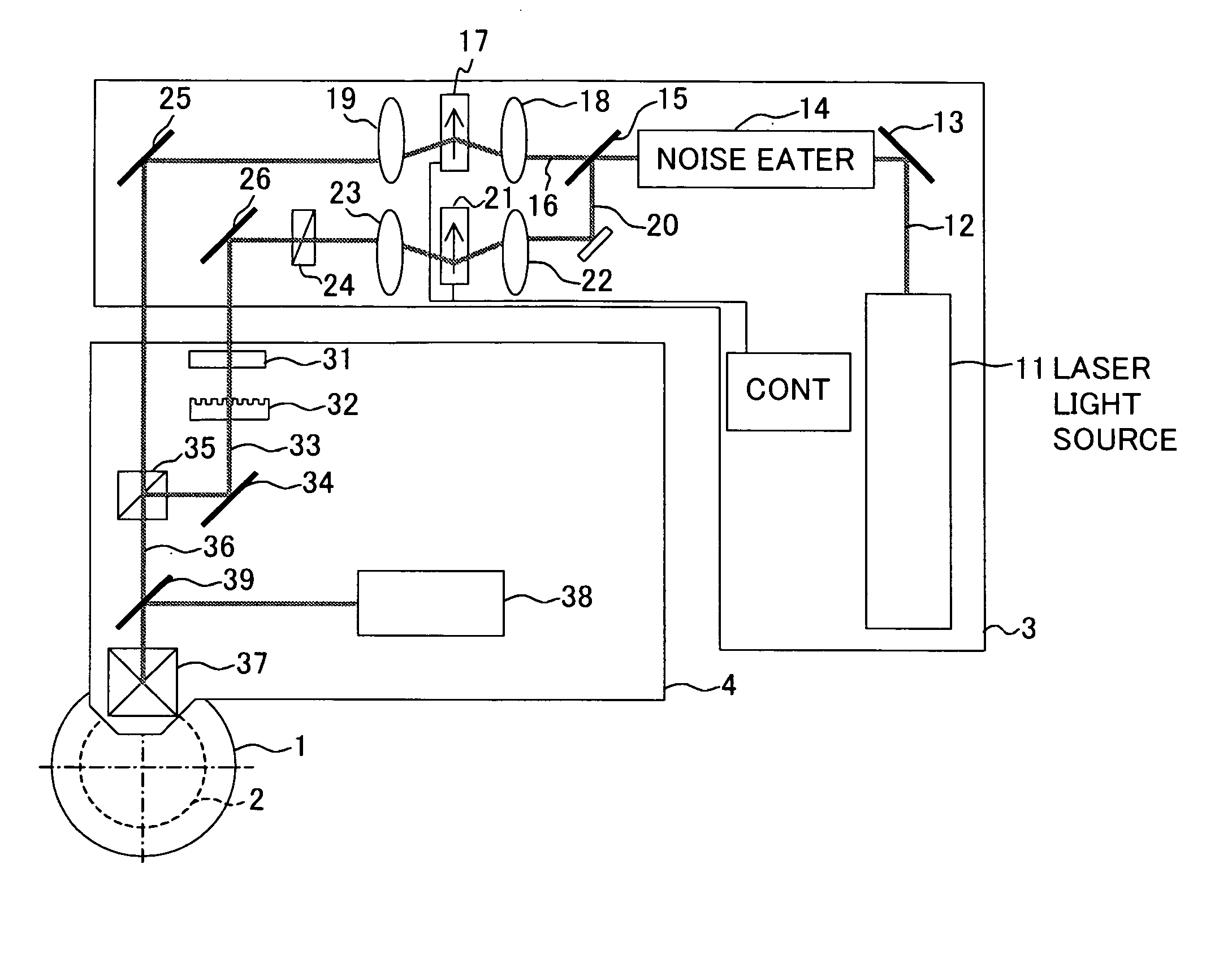
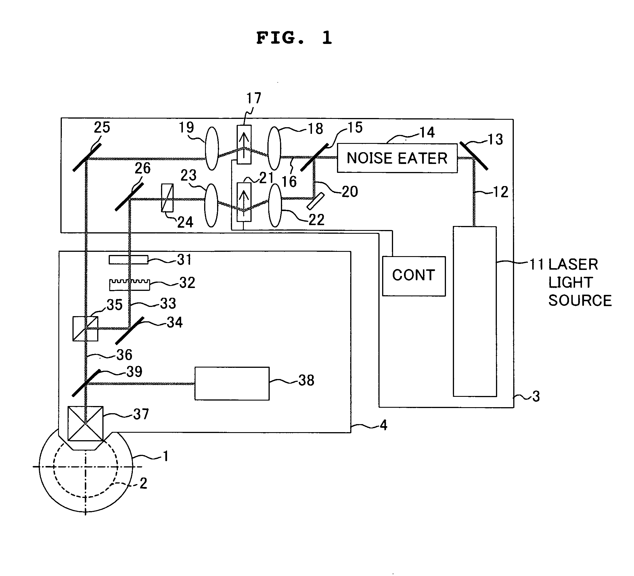
[0068] The master disk exposure apparatus, the master disk exposure method, the substrate for the information-recording medium, and the related features of the present invention will be explained below with reference to FIGS. 1 to 5 as exemplified by an exposure apparatus for a master disk for an optical disk, an exposure method for the master disk for the optical disk, and a substrate for the optical disk.

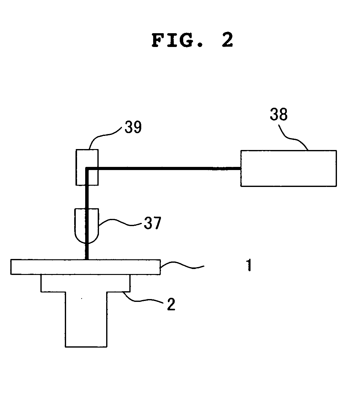
[0069] As shown in FIG. 1, a master disk exposure apparatus for an optical disk of this embodiment principally includes a master disk 1 for the optical disk, a turn table 2 which drives and rotates the master disk 1 for the optical disk, a fixed table 3 which is fixed at a predetermined position, and a movable table 4 which is arranged between the turn table 2 and the fixed table 3.

[0070] The master disk 1 for the master disk includes a photoresist layer having a uniform thickness which is formed, for example, on a surface of a smooth disk-shaped substrate made of glass.

[0071] ...

embodiment 1-2

[0084]FIG. 6 shows another specified embodiment of the master disk exposure method based on the use of the master disk exposure apparatus explained in Embodiment 1-1. In this embodiment, a pit exposure pattern was formed in the same manner as in Embodiment 1-1 except that the driving signal to be supplied to the second optical modulator was changed by using the control unit (CONT) of the master disk exposure apparatus. As shown in FIG. 6A, the same pit patterns as those in Embodiment 1-1 are formed on the tracks t1 to t3 respectively. The bit data for exposing the track t2 (FIG. 6B) and the waveform of the exposure light beam (FIG. 6C) are also the same as those in Embodiment 1-1. However, as for Beam 2, the pattern, which was reverse to that of Beam 1, was used in Embodiment 1-1. However, in this embodiment, as indicated with the track t2 in FIG. 6A, Beam 2 was also radiated on the areas P / P (2T) disposed on the both sides when the shortest pit P22 (length: 2T) was irradiated with ...

embodiment 1-3

[0088]FIG. 8 shows still another embodiment of the master disk exposure method based on the use of the master disk exposure apparatus explained in Embodiment 1-1. In this embodiment, the radiation, which is effected with Beam 1 and Beam 2 in Embodiments 1-1 and 1-2, is executed with a single laser beam by switching the power of the laser beam to the high intensity and the low intensity. Specifically, in the master disk exposure apparatus shown in FIG. 1, the driving of the second optical modulator 21 is stopped, and the modulation waveform with the first optical modulator 17 is controlled by the control unit (CONT). Accordingly, as shown in FIG. 8C, Beam 2, which has the waveform of two types of powers of the high intensity and the low intensity, is radiated. Therefore, the locus of the beam is on the track center (see the track t2) in relation to any one of the beam having the high intensity power and the beam having the low intensity power. In this embodiment, the laser intensity ...


PUM


Abstract

In Two-dimensional optical Compensation Exposure method, Beam 1, which has an intensity not less than a sensitivity of a photoresist layer and has a predetermined irradiation timing of exposed patterns, is radiated onto a predetermined area of the photoresist, and Beam 2, which has an intensity less than the sensitivity of the photoresist layer and has an irradiation timing of exposed patterns opposite to the predetermined timing, is radiated onto an area different from the predetermined area. Beam 2, which has the intensity less than the sensitivity of the photoresist layer, is radiated onto both sides P/P (2 T) in a disk radial direction of an area in which a shortest mark P22 is formed. The pit width is uniform irrelevant to the pit length. Further, it is possible to form the pit having a width shorter than a pit length. Therefore, it is possible to realize a high density.

Description

BACKGROUND OF THE INVENTION [0001] 1. Field of the Invention [0002] The present invention relates to a master disk exposure apparatus and a master disk exposure method, so called “Two-Dimensional Optical Compensation Exposure (TOCE)”. In particular, the present invention relates to a master disk exposure apparatus and a master disk exposure method which are preferably usable to produce a high recording density information-recording medium. The present invention also relates to a stamper for replicating an information-recording medium and a substrate for an information-recording medium produced by using the same. [0003] 2. Description of the Related Art [0004] In the technical field of the information-recording medium, the improvement in the recording density is a more important technical task. It has been hitherto intended to overcome such a technical task from both viewpoints, i.e., the improvement in the linear recording density to be achieved along the information track and the i...

Claims


Application Information

Patent Timeline
IPC IPC(8): G11B7/004G11B7/007G11B7/24G11B7/26
CPCG11B7/261
Inventor SUGIYAMA, TOSHINORIYOSHIOKA, TERUFUMICHIKA, YUZURUMIYATA, KATSUNORI
Owner HITACHT MAXELL LTD
Why Eureka
Try Eureka