Methods and systems for laser processing a workpiece and methods and apparatus for controlling beam quality therein

a laser processing and workpiece technology, applied in lasers, solid-state laser construction details, laser construction details, etc., can solve problems such as the inability to improve the weld nugget profil

Inactive Publication Date: 2005-05-05
GSI LUMONICS LTD
View PDF7 Cites 16 Cited by
  • Summary
  • Abstract
  • Description
  • Claims
  • Application Information

AI Technical Summary

Benefits of technology

[0019] An object of the present invention is to provide improved methods and systems for laser processing a workpiece and improved methods and apparatus for controlling beam quality therein.

Problems solved by technology

Tests have shown that using a high heat conductivity helium shield gas does not improve the weld nugget profile as it does with CO2 lasers so the mechanism appears to be different.

Method used


Image

  • Methods and systems for laser processing a workpiece and methods and apparatus for controlling beam quality therein
  • Methods and systems for laser processing a workpiece and methods and apparatus for controlling beam quality therein
  • Methods and systems for laser processing a workpiece and methods and apparatus for controlling beam quality therein

Examples


Embodiment Construction

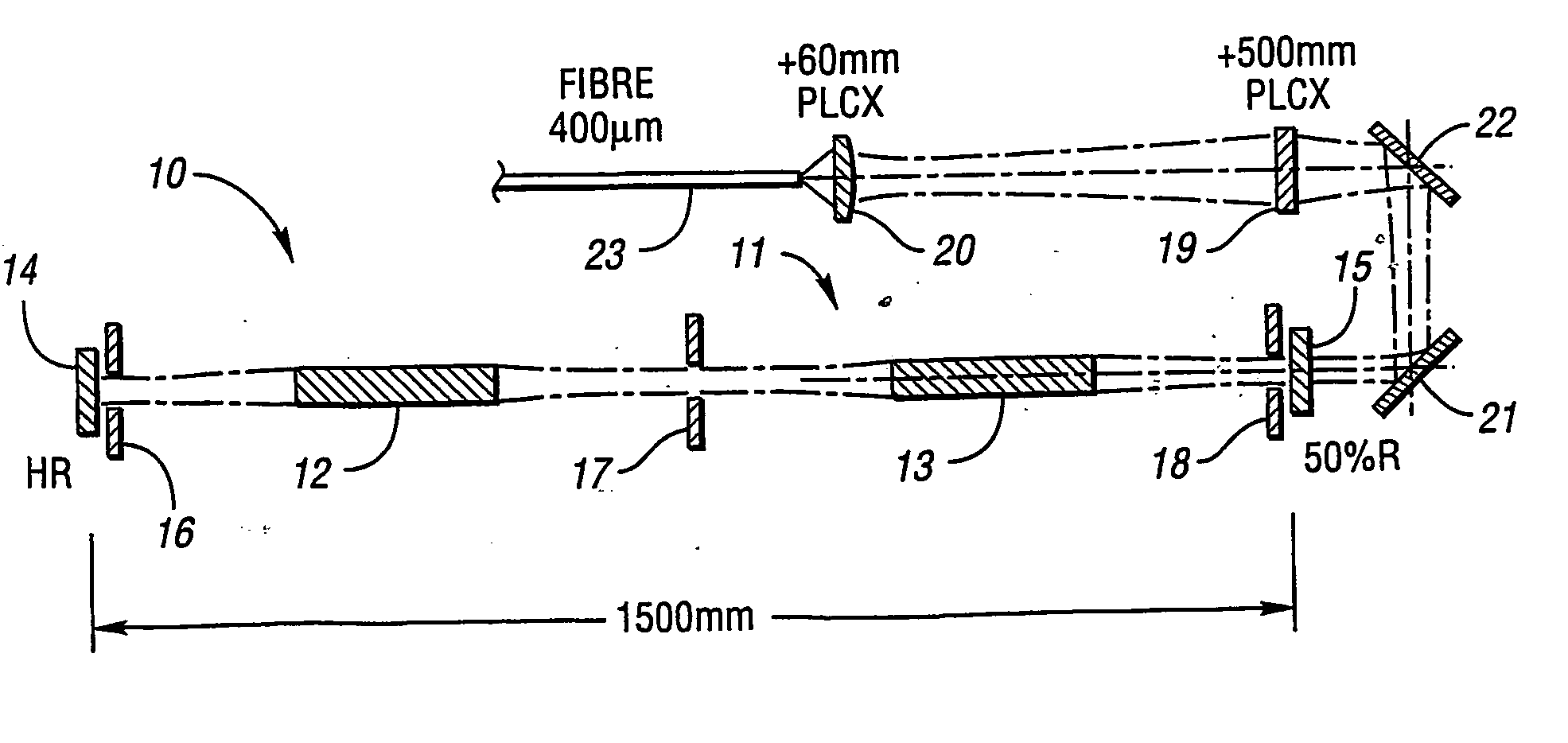
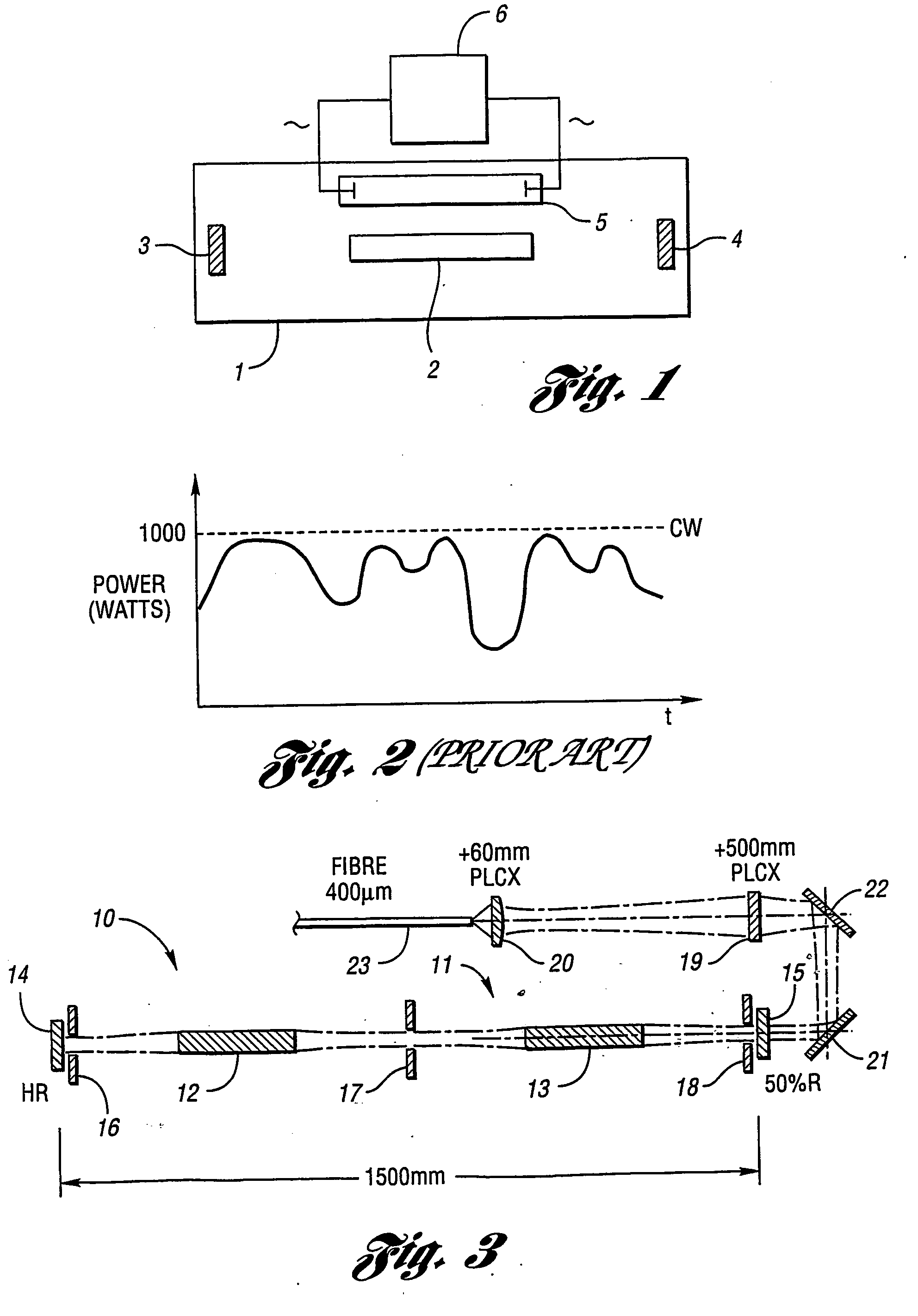
[0080]FIG. 3 shows a laser resonator. In one embodiment of the invention, this resonator includes two flooded ceramic cavities 10 and 11 each housing an Nd:YAG rod 12 and 13, respectively. Alternatively, two dry gold cavities may be used with the same AC power supply. Each chamber includes two arc lamps fitted with electrodes for AC excitation, typically up to 8 KW per lamp at 20-30 KHz. (e.g.: 15 KW total per chamber, 30 KW total lamp power).

[0081]FIG. 1, by way of example, depicts a single arc lamp 5 and an AC source 6. The resonator of FIG. 3 is formed between two flat mirrors 14 and 15 which are spaced 1500 mm apart to give a resonator pitch of 750 mm. The cavities 10 and 11 are arranged to give a symmetrical periodic resonator controlled by three apertures 16, 17 and 18 each having a 3.3 mm diameter placed at the center point and close to the mirrors 14 and 15.

[0082] The resonator output is imaged down by approximately nine times using 500 mm and 60 mm focal length lenses 19 ...


PUM

PropertyMeasurementUnit
output poweraaaaaaaaaa
diameteraaaaaaaaaa
sizeaaaaaaaaaa

Abstract

Laser processing methods, systems and apparatus having a super-modulating power supply (6) or pumping subsystem (5) and high beam quality (i.e., brightness) are disclosed. The methods, systems and apparatus have significant benefits, improved operation characteristics and material processing capability over currently available methods, systems and apparatus. In at least one embodiment, the beam quality of a high power solid state laser (2) is improved in the presence of thermal lensing. High power laser cutting, scribing, and welding results are improved with a combination of modulation and high beam quality while providing for improved processing speeds.

Description

CROSS-REFERENCE TO RELATED APPLICATIONS [0001] This application claims the benefit of U.S. Provisional Application Ser. No. 60 / 358,058, entitled “Method and System for Laser Welding”, filed 19 Feb. 2002. This application also claims the benefit of European Patent Applications EP 02 251446.7, entitled “Laser Apparatus” filed 1 Mar. 2002 and EP 02 251444.2, entitled “Laser Apparatus”, filed 1 Mar. 2002.BACKGROUND OF THE INVENTION [0002] 1. Field of the Invention [0003] This invention relates to methods and systems for laser processing a workpiece and methods and apparatus for controlling beam quality therein. An improved laser source has particular applicability to laser welding, cutting, scribing, and similar applications. [0004] 2. Background Art [0005] Continuous wave lasers (CW lasers) are commonly used in material processing applications. These are typically solid state lasers and may have Nd:YAG laser rods (laser media) or other types of laser rods. They are commonly used for ma...

Claims


Application Information

Patent Timeline
Patent Type & Authority Applications(United States)
IPC IPC(8): B23K26/06B23K26/20B23K26/28B23K26/40H01S3/02H01S3/04H01S3/06H01S3/07H01S3/08H01S3/10H01S3/13
CPCB23K26/0626B23K26/063B23K26/0643B23K26/0648B23K26/0665B23K26/365H01S3/08072H01S3/025H01S3/0407H01S3/061H01S3/0615H01S3/07H01S3/0805B23K26/407B23K26/40B23K26/0622B23K26/361B23K2103/50
Inventor HERMANN, GERALD FRANCISKUGLER, THOMAS ROBERTNAEEM, MOHAMMEDWITHNALL, KEITHGOETHALS, WALTHERFILGAS, DAVID M.
Owner GSI LUMONICS LTD
Why Eureka
Try Eureka