Fuel cell assembly gasket for fuel containment

a technology of assembly gaskets and fuel cells, which is applied in the direction of cell components, cell component details, electrochemical generators, etc., can solve the problems of reduced fuel cell efficiency, diffusional limitations, and damage from contact with flow field plates,

Inactive Publication Date: 2005-05-05
HEWLETT PACKARD DEV CO LP
View PDF9 Cites 65 Cited by
  • Summary
  • Abstract
  • Description
  • Claims
  • Application Information

AI Technical Summary

Benefits of technology

[0006] According to an embodiment, the present invention pertains to a fuel cell assembly. The fuel cell assembly includes a membrane electrode assembly having a substantially solid polymer electrolyte membrane positioned between opposed catalyst layers. The polymer electrolyte membrane has a dimension that is relatively larger than a comparable dimension of at least one of the catalyst layers, such that the polymer electrolyte membrane has an uncovered portion. The fuel cell assembly also includes a gasket attached to the uncovered portion of the polymer electrolyte membrane. The gasket extends beyond a periphery of the polymer electrolyte membrane and the gasket is formed of a polymer material. In addition, the gasket is configured to substantially prevent leakage of fuel or oxidant between an anode side and a cathode side of the membrane electrode assembly.
[0007] According to another embodiment, the invention relates to a method for substantially preventing leakage between fuel and oxidant in a fuel cell. In the method, a first polymeric gasket is attached to a first side of a polymer electrolyte membrane of the fuel cell in a manner to cause the polymeric gasket to extend beyond a periphery of a first end of the polymer electrolyte membrane. A second polymeric gasket is attached to a second side of the polymer electrolyte membrane in a manner to cause the polymeric gasket to extend beyond the periphery of the first end of the polymer electrolyte membrane. In addition, the first polymeric gasket is attached to the second polymeric gasket at a location beyond the periphery of the first end of the polymer electrolyte membrane.
[0009] The fuel cell assembly includes: means for supplying fuel to a membrane electrode assembly; means for supplying oxidant to the membrane electrode assembly; means for substantially providing fuel containment between the fuel and oxidant in at least one area beyond a periphery of the membrane electrode assembly, wherein the means for providing fuel containment between the fuel and oxidant comprises a polymeric material; and means for attaching the means for substantially preventing cross-over to the membrane electrode assembly.
[0010] According to yet another embodiment, the present invention pertains to a fuel cell assembly. The fuel cell assembly includes a first gasket layer and a second gasket layer attached to each other to form a cavity therebetween. A liquid electrolyte is housed in the cavity formed between the first and second gasket layers, wherein the first and second gasket layers are configured to substantially prevent leakage of the liquid electrolyte from the cavity. In addition, the first and second gasket layers extend beyond a periphery of the liquid electrolyte and the gasket is configured to substantially prevent leakage of fuel or oxidant between an anode side and a cathode side of the liquid electrolyte.

Problems solved by technology

The escape of fuel through the periphery or edge of the water transport plates or electrode substrates typically results in the loss of the respective media, thereby causing a decrease in the fuel cell efficiency.
However, in this type of construction, problems related to crushed gas diffusion layers, diffusional limitations, and damage from contact with the flow field plate often arises.
In addition, it is often difficult to align the gaskets with a membrane exchange assembly (MEA) and the size of the mechanical fasteners typically precludes them from being suitable for use in relatively slim applications.
This construction method suffers from the disadvantage of being tedious, time consuming and expensive.
These seals are relatively stiff and require high sealing loads.
As a result, this known method of construction typically provides unacceptable sealing performance.

Method used


Image

  • Fuel cell assembly gasket for fuel containment
  • Fuel cell assembly gasket for fuel containment
  • Fuel cell assembly gasket for fuel containment

Examples


Embodiment Construction

[0021] For simplicity and illustrative purposes, the present invention is described by referring mainly to an exemplary embodiment thereof. In the following description, numerous specific details are set forth in order to provide a thorough understanding of the present invention. It will be apparent however, to one of ordinary skill in the art, that the present invention may be practiced without limitation to these specific details. In other instances, well known methods and structures have not been described in detail so as not to unnecessarily obscure the present invention.

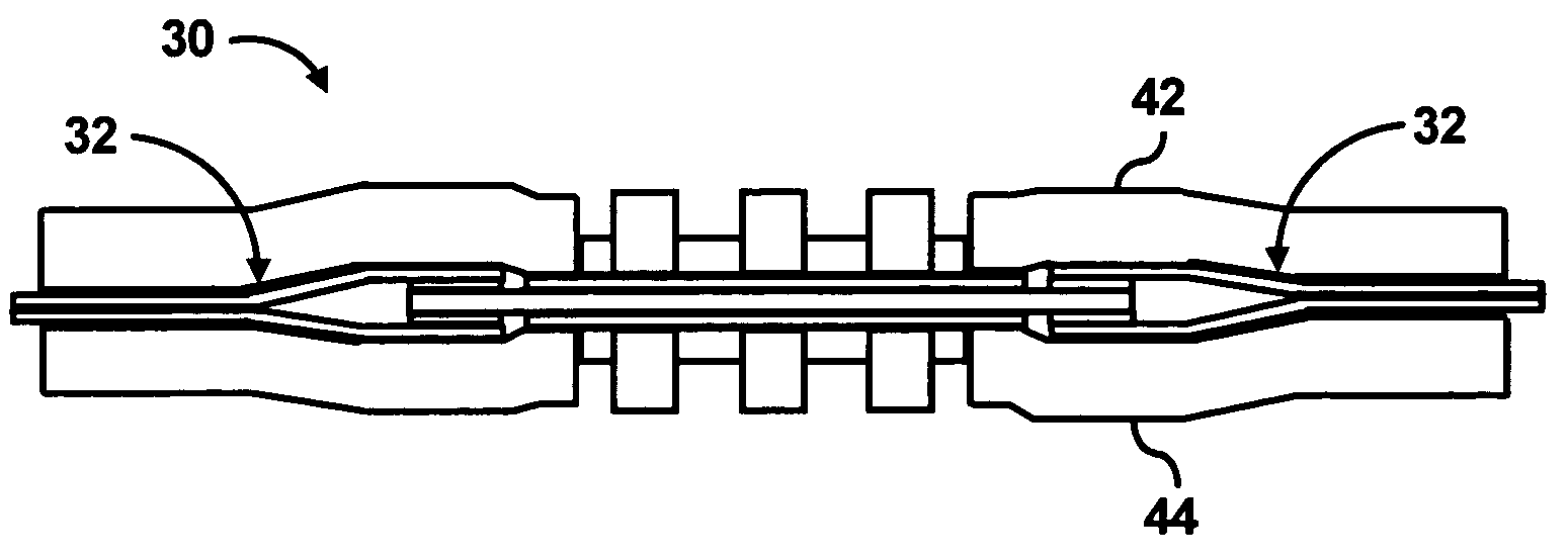
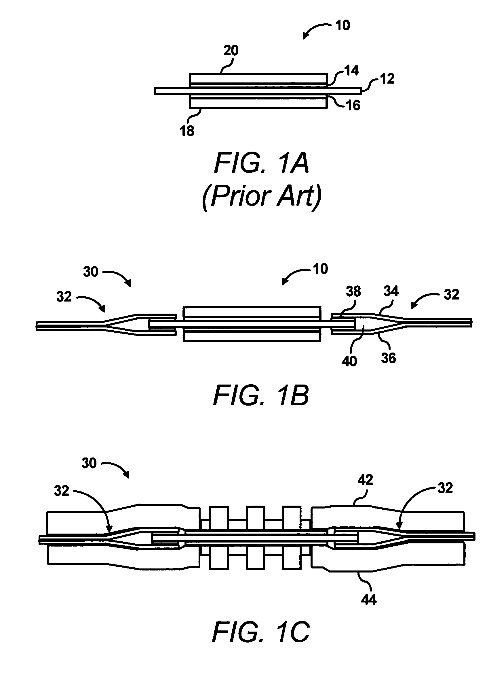
[0022] According to an embodiment of the invention, a seal or gasket is provided around an edge of a proton exchange membrane, or a polymer electrolyte membrane, (PEM) to substantially prevent leakage between fuel and oxidant. Throughout the present disclosure, the terms “seal” and “gasket” are used interchangeably and may be defined as elements designed to substantially prevent escape of gas or fluids. The gas...


PUM

PropertyMeasurementUnit
dimensionaaaaaaaaaa
heightaaaaaaaaaa
heightsaaaaaaaaaa

Abstract

A fuel cell assembly includes a membrane electrode assembly having a substantially solid polymer electrolyte membrane positioned between opposed catalyst layers. The polymer electrolyte membrane has a dimension that is relatively larger than a comparable dimension of at least one of the catalyst layers, such that the polymer electrolyte membrane has an uncovered portion. The fuel cell assembly also includes a gasket attached to the uncovered portion of the polymer electrolyte membrane. The gasket extends beyond a periphery of the polymer electrolyte membrane and the gasket is formed of a polymer material. In addition, the gasket is configured to substantially seal the edges of the polymer electrolyte membrane to substantially prevent leakage of fuel or oxidant between an anode side and a cathode side of the membrane electrode assembly.

Description

BACKGROUND OF THE INVENTION [0001] Proton exchange membrane, or polymer electrolyte membrane, (PEM) fuel cells employ a relatively simple chemical process to combine hydrogen and oxygen into water and produces electric current in the process. The general principles of construction and operation of PEM fuel cells are so well known that they need not be discussed in great detail. [0002] In general, in PEM fuel cells, a fuel with an oxidant is converted to electric energy in the presence of a catalyst. The fuel is supplied to an anode and the oxidant is supplied to a cathode. The two electrodes are connected within the fuel cell by an electrolyte to transmit protons from the anode to the cathode. The supply of fuel and oxidant is distributed as uniformly as possible over the active surfaces of the respective electrodes, or, more specifically, the electrode surfaces facing the PEM, each of which typically includes a catalyst layer thereon. An electrochemical reaction takes place at and ...

Claims


Application Information

Patent Timeline
Patent Type & Authority Applications(United States)
IPC IPC(8): H01M8/02H01M8/10H01M8/24
CPCH01M8/0271H01M8/0273Y02E60/521H01M8/242H01M8/1004H01M8/2418Y02E60/50
Inventor MITTELSTADT, LAURIE S.JEON, YOOCHARNPAN, ALFRED
Owner HEWLETT PACKARD DEV CO LP
Why Eureka
Try Eureka