Highly sensitive accelerometer

a high-sensitivity, accelerometer technology, applied in the direction of acceleration measurement using interia force, optical radiation measurement, instruments, etc., can solve the problems of difficult to provide, many prior accelerometer designs are unacceptable, and electrical accelerometers are difficult to provid

Inactive Publication Date: 2005-05-12
WEATHERFORD TECH HLDG LLC
View PDF28 Cites 54 Cited by
  • Summary
  • Abstract
  • Description
  • Claims
  • Application Information

AI Technical Summary

Benefits of technology

[0010] Embodiments of the invention generally relate to accelerometers for determining acceleration and methods of fabricating an accelerometer. In one embodiment, the accelerometer includes a frame, a mass movably suspended on the frame, a fixed element having a rounded surface that does not move with respect to the frame, a movable element having a rounded surface that moves with the mass, and a sensing coil of optical waveguide wrapped around the rounded surfaces to detect movement of the mass in response to acceleration based on interferometric sensing of a change in length of the sensing coil. A method of fabricating the accelerometer includes suspending the mass in the frame and wrapping the optical waveguide around the rounded surfaces. Sensitivity and low fabrication cost of the accelerometers enables their use for integration within an ocean bottom seismic cable. Further, the accelerometer may be an in-line or a cross-line accelerometer depending on the arrangement within the frame.

Problems solved by technology

Thus, the sensitivity of the accelerometer directly affects the quality of the data acquired by the OBS survey making many prior accelerometers designs unacceptable due to insufficient sensitivity.
Several problems exist with using conventional electrical accelerometers in cable arrays in the ocean.
In particular, electrical accelerometers require an insulated electrical conductor for transmitting electrical signals, which can short if the electrical conductor becomes damaged and is exposed to sea water.
Further, most high performance piezoelectric accelerometers require power at the sensor head which may be difficult to provide due to the substantial cable length.
Also, multiplexing of a large number of such sensors is not only cumbersome but tends to occur at a significant increase in weight and volume of an accelerometer array, as well as a decrease in reliability.
Additionally, piezoelectric accelerometers tend to operate poorly at the lowest frequencies in the seismic band.
Many systems and methods for OBS surveying do not retrieve the cable arrays for redeployment and reuse.
The large quantity of accelerometers required along with the practice of abandoning the deployed cable arrays after one use makes the cost of the accelerometers very critical.
Prior designs of both optical and electrical accelerometers often require a complicated assembly procedure and a large number of specially made parts, thereby increasing the cost to manufacture the accelerometers.

Method used


Image

  • Highly sensitive accelerometer
  • Highly sensitive accelerometer
  • Highly sensitive accelerometer

Examples


Embodiment Construction

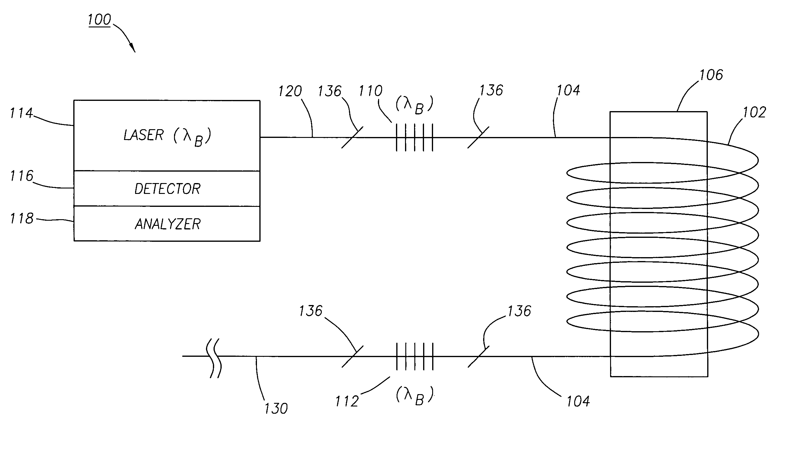
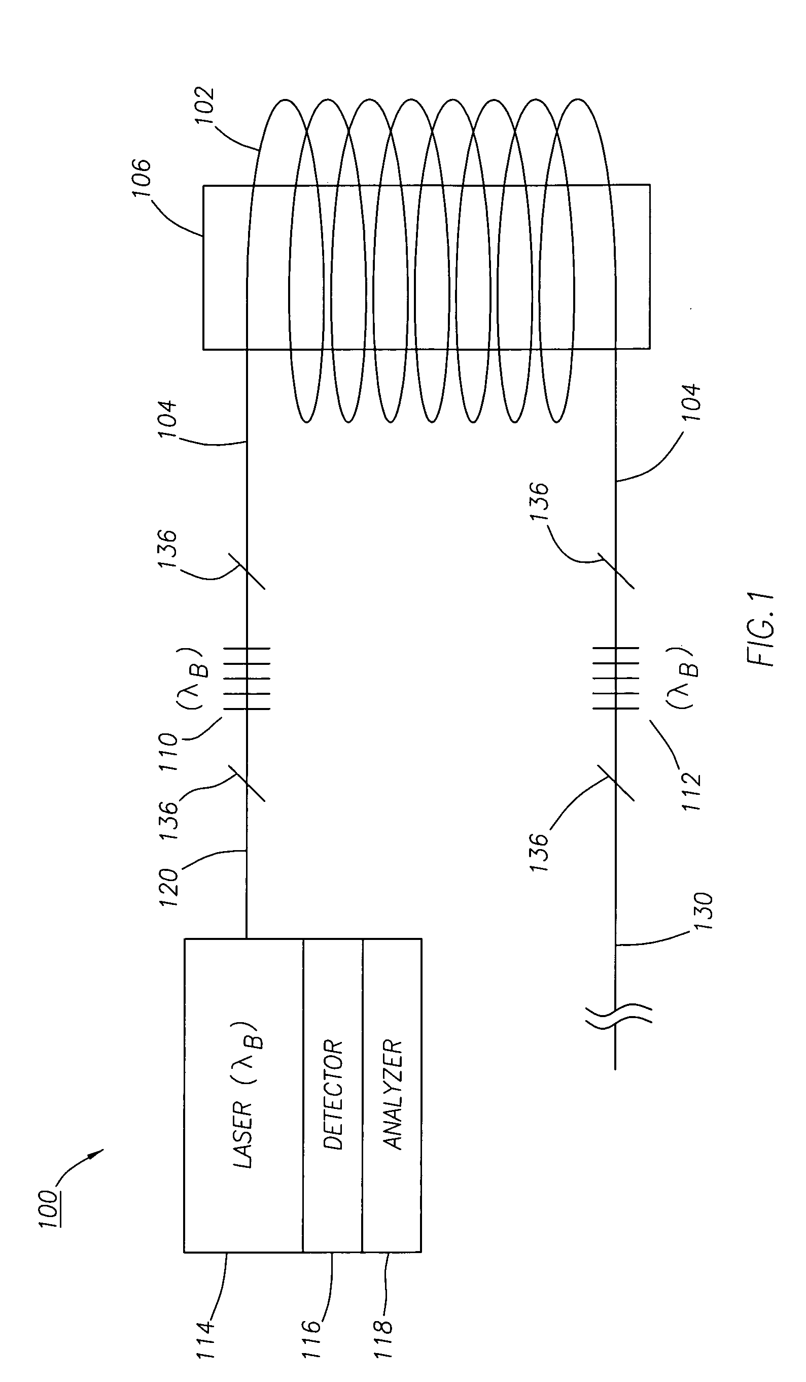
[0028] Embodiments of the invention generally relate to an optical accelerometer. The accelerometer may be coupled to any surface or structure subjected to acceleration to be sensed. In one particular application, the highly sensitive accelerometers described herein may be disposed within sensor stations spaced along a seismic cable used to obtain an ocean bottom seismic (OBS) survey. As described in greater detail herein for some embodiments, each accelerometer may include a pair of fiber optic sensors separated by a length of optical fiber, forming an interferometer. Each sensor in the pair may reflect a narrow wavelength band of light having a central wavelength. Each accelerometer may operate at a different wavelength band and central wavelength such that the signals may be easily detected using Wavelength Division Multiplexing (WDM) techniques. Alternatively, the signals may be separated in time using Time Division Multiplexing (TDM).

[0029]FIG. 1 schematically illustrates a si...


PUM


Abstract

Accelerometers for determining acceleration and methods of fabricating an accelerometer are disclosed. In one embodiment, the accelerometer includes a frame, a mass movably suspended on the frame, a fixed element having a rounded surface that does not move with respect to the frame, a movable element having a rounded surface that moves with the mass, and a sensing coil of optical waveguide wrapped around the rounded surfaces to detect movement of the mass in response to acceleration based on interferometric sensing of a change in length of the sensing coil. A method of fabricating the accelerometer includes suspending the mass in the frame and wrapping the optical waveguide around the rounded surfaces. Sensitivity and low fabrication cost of the accelerometers enables their use for integration within an ocean bottom seismic cable. Further, the accelerometer may be an in-line or a cross-line accelerometer depending on the arrangement within the frame.

Description

CROSS-REFERENCE TO RELATED APPLICATIONS [0001] This application is a continuation-in-part of co-pending U.S. patent application Ser. No. 10 / 933,132 filed on Sep. 2, 2004, which is a continuation of U.S. Pat. No. 6,789,424, which is a continuation of U.S. Pat. No. 6,575,033, filed Oct. 1, 1999, each herein incorporated by reference.BACKGROUND OF THE INVENTION [0002] 1. Field of the Invention [0003] Embodiments of the present invention generally relate to highly sensitive accelerometers. More particularly, embodiments of the invention relate to optical accelerometers for applications such as integration into ocean bottom seismic cables. [0004] 2. Description of the Related Art [0005] Marine seismic exploration surveys for the exploration and monitoring of hydrocarbon producing zones and reservoirs utilize seismic cables deployed on the ocean floor. The cable includes an array of accelerometers capable of detecting ground acceleration on the ocean floor produced by acoustic vibrations....

Claims


Application Information

Patent Timeline
Patent Type & Authority Applications(United States)
IPC IPC(8): G01P15/093G01V1/18
CPCG01H9/004G01V2210/1427G01V1/181G01P15/093G01V1/18
Inventor BERG, ARNEHEGLUM, TORBJOERN
Owner WEATHERFORD TECH HLDG LLC
Why Eureka
Try Eureka