
Method for HVOF or LPPS restoration coating repair of a nickel-base superalloy article

Inactive Publication Date: 2005-05-12
GENERAL ELECTRIC CO
View PDF8 Cites 18 Cited by
  • Summary
  • Abstract
  • Description
  • Claims
  • Application Information

AI Technical Summary

Benefits of technology

[0012] In the step of heating to effect diffusion bonding, the article is preferably heated to a temperature of at least 1950° F., more preferably to a temperature of from about 2025° F. to about 2075° F., an

Problems solved by technology

However, the restoration alloy is not necessarily a nickel-base superalloy and, if it is, the restoration alloy need not be heat treated to produce gamma prime precipitates.

Method used


Image

  • Method for HVOF or LPPS restoration coating repair of a nickel-base superalloy article
  • Method for HVOF or LPPS restoration coating repair of a nickel-base superalloy article
  • Method for HVOF or LPPS restoration coating repair of a nickel-base superalloy article

Examples


Embodiment Construction

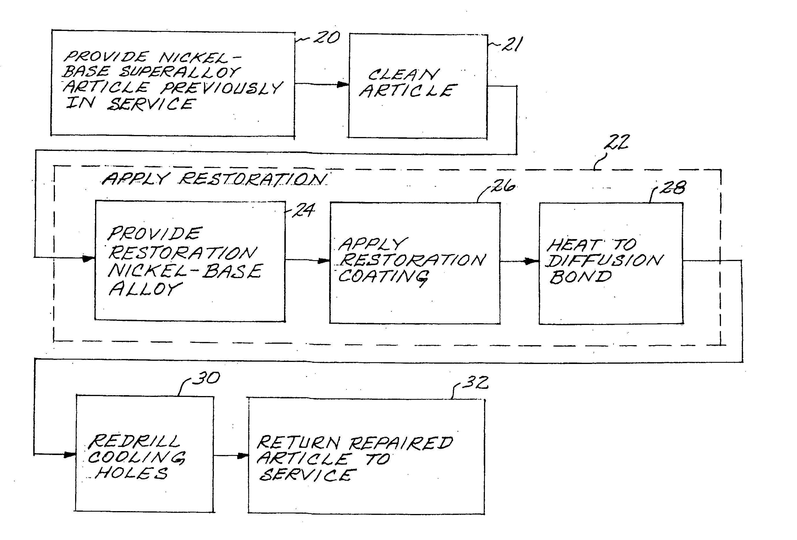
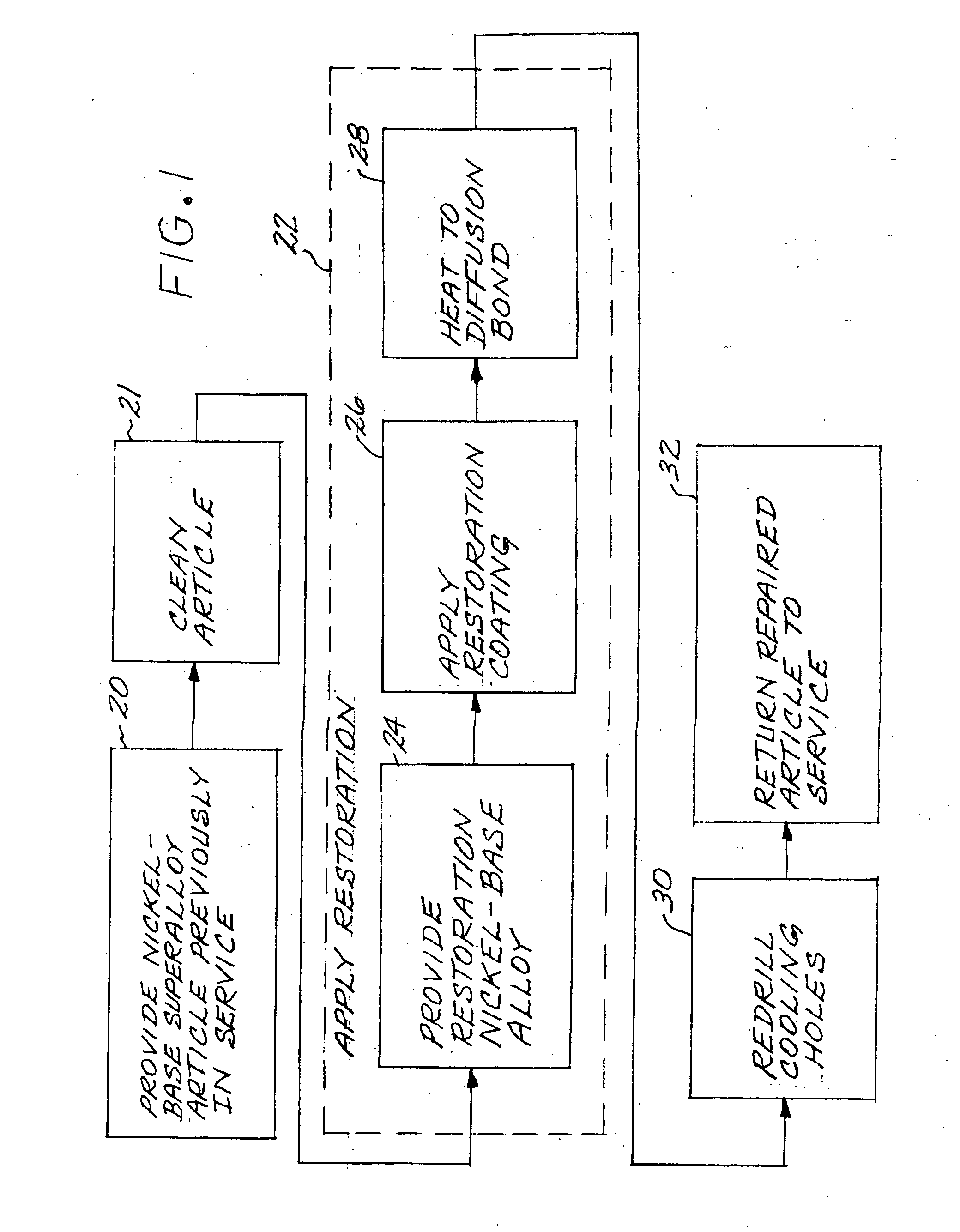
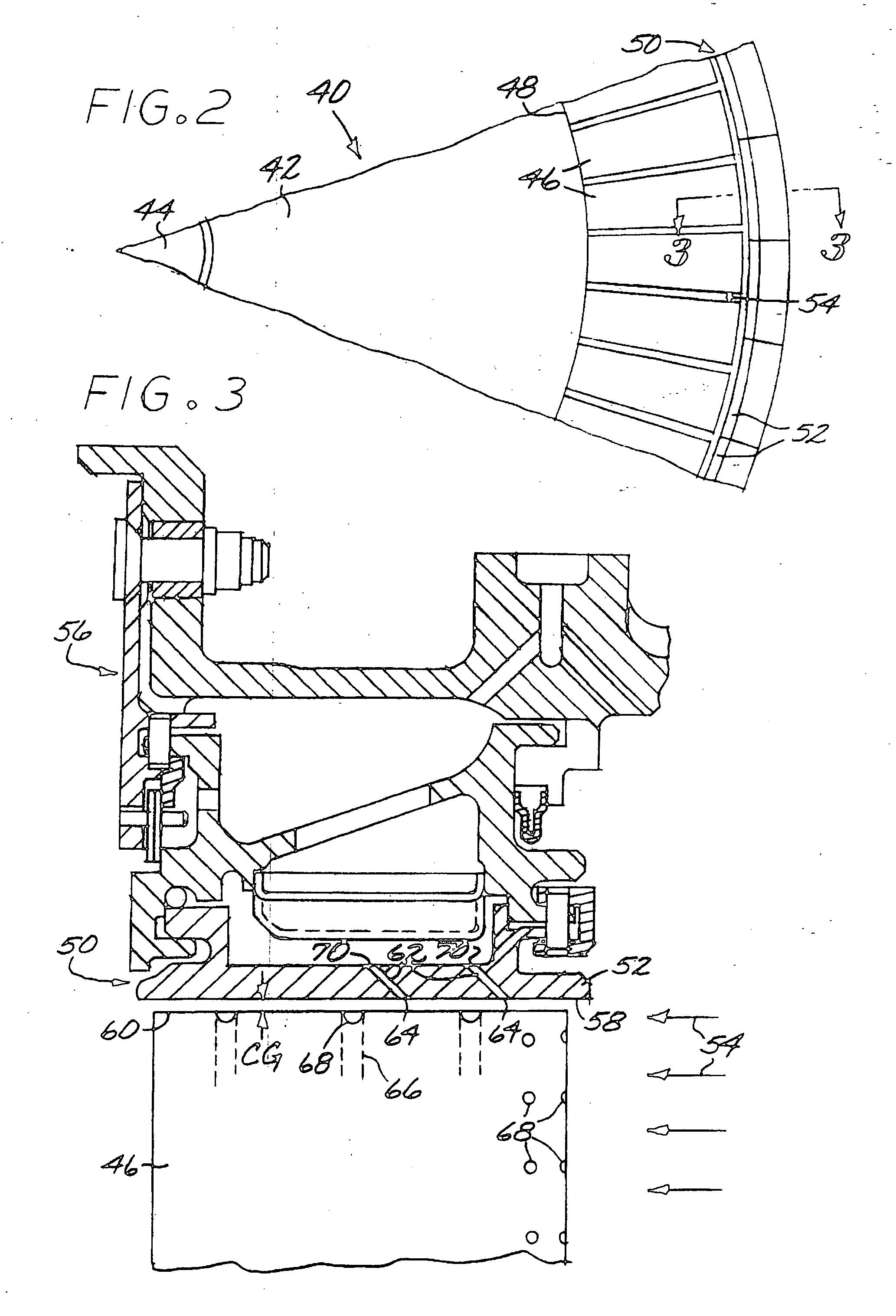
[0022]FIG. 1 depicts in block diagram form a preferred embodiment of a method for repairing a nickel-base superalloy article. In practicing the method, the nickel-base superalloy article that has previously been in service is provided, step 20. The present approach is applicable to any operable article. FIGS. 2-7 depict the use of the method in relation to a presently preferred article, a gas turbine stationary flowpath shroud.

[0023]FIG. 2 presents a simplified depiction of the relevant portions of a gas turbine 40 illustrating only the components of interest. The gas turbine 40 includes a turbine disk 42 that is fixed to and rotates with a center shaft 44. A plurality of turbine blades 46 extend radially outwardly from a periphery 48 of the turbine disk 42. A gas turbine stationary flowpath shroud 50 forms a tunnel-like structure in which the turbine disk 42, the shaft 44, and the turbine blades 46 turn. (The gas turbine stationary flowpath shroud 50 is termed “stationary” and doe...


PUM

PropertyMeasurementUnit
Temperatureaaaaaaaaaa

Abstract

A method for repairing a nickel-base superalloy article, such as a gas turbine stationary flowpath shroud having flowpath cooling holes therein that has previously been in service, includes the steps of providing the nickel-base superalloy article that has previously been in service; and applying a restoration to a surface of the article. The restoration is applied by the steps of providing a restoration nickel-base alloy, wherein the restoration nickel-base alloy preferably has no more than about 15 weight percent chromium and no more than about 0.01 percent yttrium, thereafter applying a restoration coating of the restoration nickel-base alloy to the surface of the article by a hyper-velocity oxyfuel metal spray process or a low-pressure plasma spray process, and thereafter heating the article with the restoration coating applied to the surface thereof to a sufficiently high temperature to diffusion bond the restoration coating to the surface of the article. The article is then returned to service.

Description

[0001] This invention relates to the repair of a nickel-base superalloy article and, more particularly, to a repair for restoring a dimension of the article. BACKGROUND OF THE INVENTION [0002] In an aircraft gas turbine (jet) engine, air is drawn into the front of the engine, compressed by a shaft-mounted compressor, and mixed with fuel. The mixture is combusted, and the resulting hot combustion gas is passed through a turbine mounted on the same shaft. The turbine includes a rotating turbine disk with turbine blades supported on its periphery, and a stationary (that is, not rotating) gas turbine flowpath shroud that confines the combustion gas to flow through the annulus between the turbine disk and the shroud, and thence against the turbine blades. The constrained flow of hot combustion gas turns the turbine by contacting an airfoil portion of the turbine blade, which turns the shaft and provides power to the compressor. The rotating turbine blades and the gas turbine stationary f...

Claims


Application Information

Patent Timeline
IPC IPC(8): B23K10/02B23P6/00C22F1/10C23C4/04C23C4/12C23C4/18
CPCB23K10/027B23K2201/001C23C4/18B23P6/007C23C4/124B23K2203/08C23C4/129B23K2101/001B23K2103/26C23C4/04C23C4/12
Inventor BUDINGER, DAVID EDWINTHOLKE, BRENT ROSSMILLER, MATTHEW NICKLUSGROSSKLAUS, WARREN DAVIS JR.MILLER, JOSHUA LEIGHJACKSON, MELVIN ROBERT
Owner GENERAL ELECTRIC CO
Learn More