Apparatus and method for electron beam irradiation having improved dose uniformity ratio

a technology of electron beam and apparatus, which is applied in the direction of photoelectric discharge tubes, packaging sterilisation, bottling operations, etc., can solve the problems of affecting the treatment effect of given products, affecting the effect of irradiation, and progressively losing electron energy, etc., to achieve optimal configuration, improve the dose uniformity ratio, and improve the effect of dur

Inactive Publication Date: 2005-05-12
ION BEAM APPL
View PDF6 Cites 9 Cited by
  • Summary
  • Abstract
  • Description
  • Claims
  • Application Information

AI Technical Summary

Benefits of technology

[0018] transporting said product package along said transport path, under said radiation beam, whereby part of said radiation beam is reflected on sides of said product package. Preferably, the method comprises the step of adjusting the distance of said reflection means to said transport path according to the size of the product package, for minimizing the distance between said reflection means and said product package.

Problems solved by technology

Due to the non-uniformity of dose in the product (high DUR), a given product may not be treatable at a given facility because the maximum acceptable dose would be exceeded at some place while the lowest dose in the product is at the lower limit.
These electrons progressively lose their energy, and consequently deposit some dose in the material.
In this configuration, the above side-effect may be limited by having product packages in close contact to each other in the conveyor direction.
However, this requires a control system for the conveyor ensuring successive product packages are in contact with each other, including the first and last package of a batch of packages, and the side-effect remains for the sides of the product package along the conveyor direction.
However, this design is far from optimal in the reduction of the side effect, i.e. one still observes a dose fall-off on the lateral sides of the package.
Moreover, this device lacks versatility in that it cannot be adapted to packages of variable widths.
However, this apparatus neither provides a good throughput nor a significantly improved DUR.
Because of the scatter plate, a significant fraction of the accelerator power is lost in the scatter plate.
Obviously, the sizes of the product packages and the reflecting baskets must match, which limits the flexibility of said apparatus and method.
The presence of angled side scatter plates along the front and rear side of the product package in the direction of conveyor travel additionally reduces the throughput of this installation.
Moreover, the selection of the angles of the angled side scatter plates is far from optimal.

Method used


Image

  • Apparatus and method for electron beam irradiation having improved dose uniformity ratio
  • Apparatus and method for electron beam irradiation having improved dose uniformity ratio
  • Apparatus and method for electron beam irradiation having improved dose uniformity ratio

Examples


Embodiment Construction

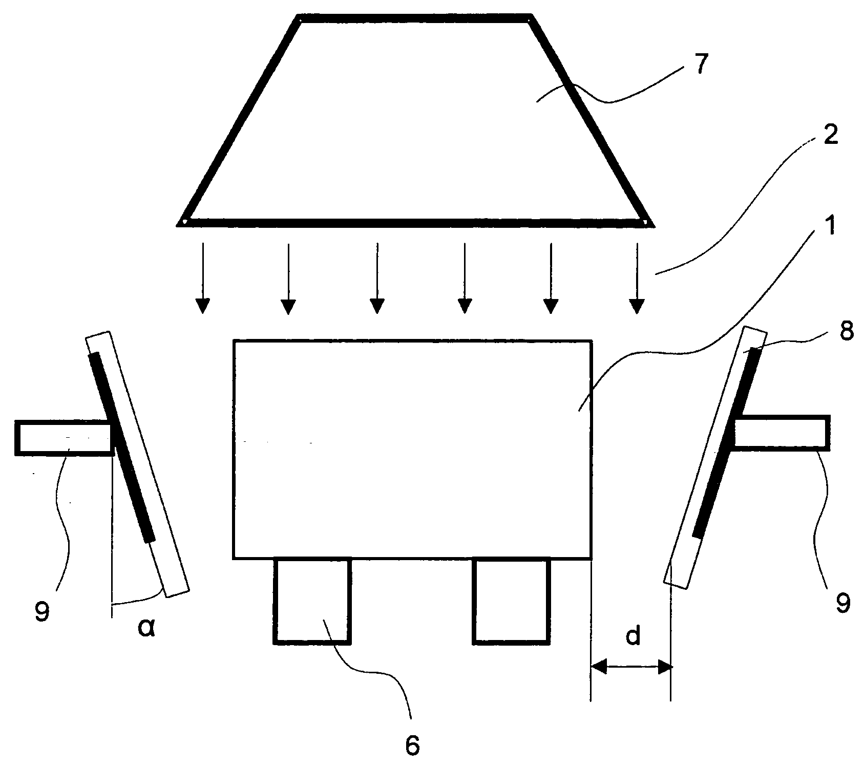
[0029]FIG. 3 represents a section view with the section taken perpendicular to the transport path of a first embodiment according to the invention. A product package 1 is transported by a conveyor 6. The conveyor 6 may be any conventional conveyor system, such as a chain conveyor or a roller conveyor. Motor means and control means are provided for transporting the product package under the beam at a controlled speed. A scan horn 7 above the product package provides a beam of electrons, either parallel or divergent. The width of the electron beam 2 at the top layer of the product package 1 is larger than the width of the product package. Reflecting means 8 are installed on both sides of the conveyor path. These reflector means are rectangular sheets of material. Materials used for the reflectors should preferably have good electrical and thermal conduction as well as good mechanical properties. Materials with high Z will be more efficient to reflect radiations. Metallic materials wit...


PUM

PropertyMeasurementUnit
angleaaaaaaaaaa
densityaaaaaaaaaa
densityaaaaaaaaaa

Abstract

The present invention is related to an apparatus and method for irradiating a product package, comprising a radiation source directing a radiation beam along a beam direction towards said product package, conveying means for transporting said product package past said radiation source along a transport path, and reflecting means located on at least one side of the plane formed by said beam direction and said transport path. By adjusting the distance and angle of the reflecting means to the conveyor and beam, and improved dose uniformity ratio is obtained.

Description

FIELD OF THE INVENTION [0001] The present invention is related to an apparatus and method for electron beam irradiation wherein an improved dose uniformity ratio in irradiated products can be obtained. STATE OF THE ART [0002] Irradiation is used to treat many types of products and articles, e.g. for sterilising medical devices, or for pasteurising food. Irradiation is also used for polymerization of liquid monomers or degradation or cross-linking of polymers. [0003] Depending on the level of dose required for achieving an effect, and the type of irradiation source available, one uses gamma rays, electron beams or x-rays. These radiation types have very different properties as to penetration in matter, and the production methods are also very different (see “Radiation Sterilization for Health Care Products”, B. P. Fairand, CRC Press, 2002). [0004] An irradiation process is often specified by a minimum absorbed dose to achieve the desired effect and a maximum dose limit that the produ...

Claims


Application Information

Patent Timeline
Patent Type & Authority Applications(United States)
IPC IPC(8): A61L2/08B65B55/08B65B55/16
CPCA61L2/087A61L2202/23B65B55/16B65B55/08
Inventor BOL, JEAN LOUISGREGOIRE, OLIVIERMARTIN, FRANCISMULLIER, BENOITSTICHELBAUT, FREDERIC
Owner ION BEAM APPL
Why Eureka
Try Eureka