Backlighting system for liquid crystal displays

a liquid crystal display and backlighting technology, applied in the direction of display means, identification means, instruments, etc., can solve the problems of inability to compensate the shift in the color position of the luminance, the shift in the color position will be obvious and annoying to the user, and the technique is expensive and time-consuming. achieve the effect of simple and effectiv

Inactive Publication Date: 2005-05-12
SIEMENS AG
View PDF8 Cites 19 Cited by
  • Summary
  • Abstract
  • Description
  • Claims
  • Application Information

AI Technical Summary

Benefits of technology

[0011] Thus, one object of the present invention is to provide a backlighting system that ensures a constant distri

Problems solved by technology

As a result, it is not possible to compensate the shift in the color location of the luminance caused by manufacturing tolerances by a slight change in the operating point.
Such color location shifts will be obvious and annoying to a user especially if several liquid crystal displays are arranged side

Method used


Image

  • Backlighting system for liquid crystal displays
  • Backlighting system for liquid crystal displays
  • Backlighting system for liquid crystal displays

Examples


Embodiment Construction

[0024] The present invention will now be described in detail by describing illustrative, non-limiting embodiments thereof with reference to the accompanying drawings._In the drawings, the same reference characters denote the same elements.

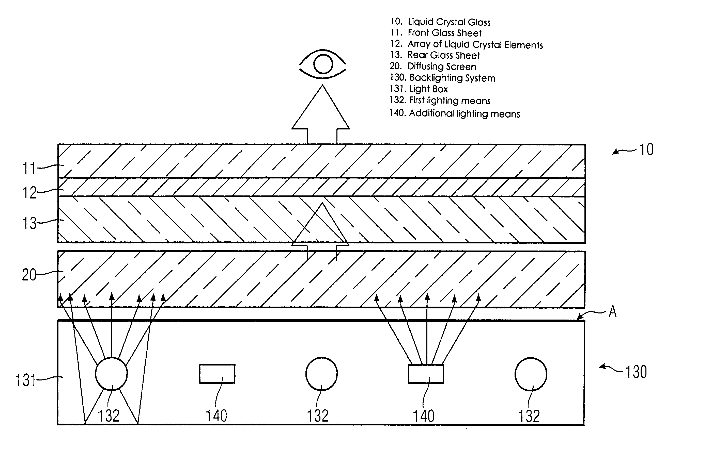
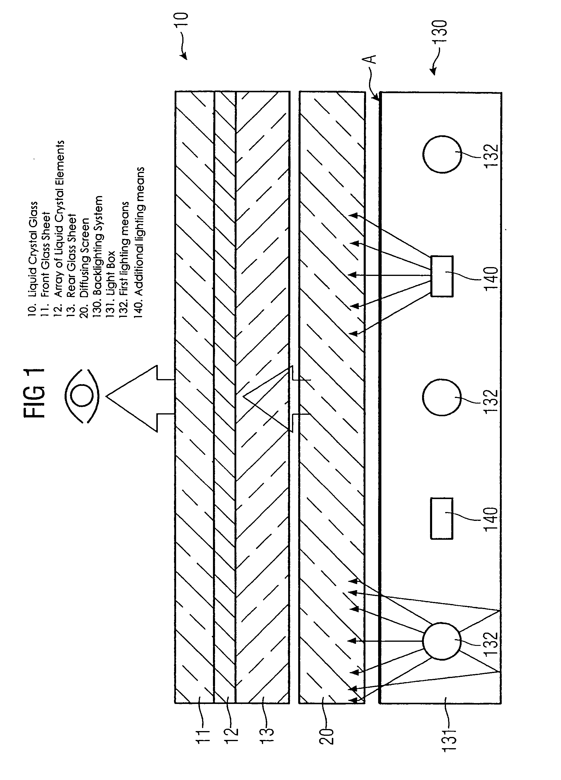
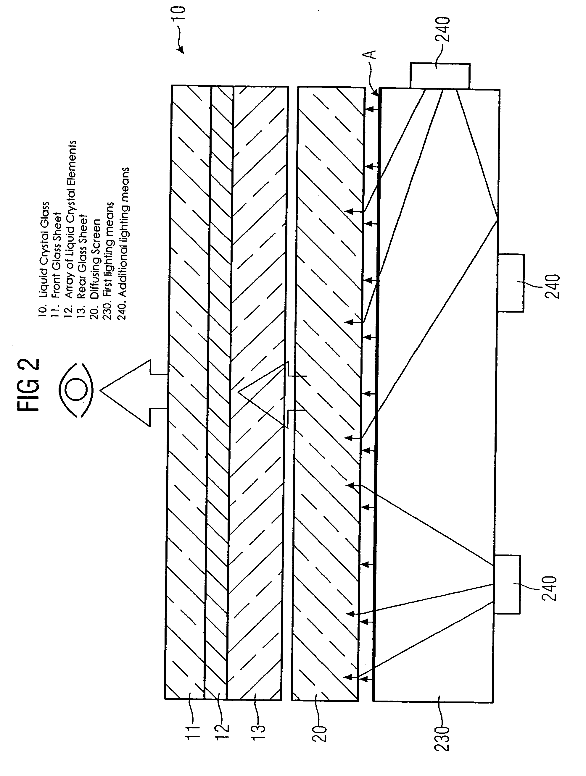
[0025] A liquid crystal displays, as illustrated in FIG. 1 has a liquid crystal glass 10 in which an array 12 of liquid crystal elements is sandwiched between a front glass sheet 11 and a rear glass sheet 13. The size, number and arrangement of the liquid crystal elements determine the display area for representing an image. To display images, the transmittance of the individual liquid crystal elements is controlled. The details regarding the structure of the liquid crystal glass 10, their control and the representation of images by means of such liquid crystal displays will not be further explained here. These details are generally known and do not significantly contribute to the concept of the present invention.

[0026] Usually, a backlighting sy...


PUM


Abstract

A backlighting system for liquid crystal displays includes one or more first lighting structure (130, 230), which has a defined radiant flux with spectral color components at one operating point. The radiant flux output from the first lighting structure (130, 230) exits across a radiant surface (A) of the backlighting system and thus provides a defined luminous flux with spectral color components on a liquid crystal glass (10) that can be arranged in front of this radiant surface (A). Also, the backlighting system has one or more additional lighting structure (140, 240, 340). The radiant flux of the additional lighting structure varies. This additional lighting structure (140, 240, 340) is arranged such that the spectral color components of the luminous flux change when the radiant flux of the additional lighting structure (140, 240, 340) is changed. The liquid crystal display is used for controlling and monitoring in an automation system.

Description

[0001] The following disclosure is based on German Patent Application No. 103 38 691.2, filed on Aug. 22, 2003, which is incorporated into this application by reference. FIELD AND BACKGROUND OF THE INVENTION [0002] 1. Field of the Invention [0003] The present invention relates to a backlighting system for liquid crystal displays and to a liquid crystal display with the backlight system. [0004] 2. Description of Related Art [0005] Liquid crystal displays and their use are generally known. Conventional cathode ray tube monitors are increasingly replaced by liquid crystal displays. Such liquid crystal displays, also referred to as LCD displays, are used, in particular, wherever space is limited. [0006] Liquid crystal displays essentially consist of a so-called liquid crystal glass in which a number of liquid crystal elements are bound in a form of a suitable matrix between two sheets of glass. Depending on the type of liquid crystals used, monochrome or color LCD displays can be made. ...

Claims


Application Information

Patent Timeline
IPC IPC(8): F21V7/04G02F1/13357G09F9/35
CPCG02F1/133603G02F2001/133613G02F1/133609G02F1/133604G02F1/133613
Inventor NAGEL, UWE
Owner SIEMENS AG
Why Eureka
Try Eureka