Packet switching system

a packet switching and switching line technology, applied in the field of internal structure, can solve the problems of increasing the loss of signal transmission, the inability to avoid the extension of the network processor to a certain length, and the internal packet forwarding process congestion, so as to achieve the effect of reducing size, high performance and cost reduction

Inactive Publication Date: 2005-05-12
HITACHI LTD
View PDF7 Cites 30 Cited by
  • Summary
  • Abstract
  • Description
  • Claims
  • Application Information

AI Technical Summary

Benefits of technology

[0014] This is why the present invention can realize a packet switching system that can cope with an expansion of the communication traffic and even changes of the communication environment flexibly without causing any congestion in the forwarding of packets in the system itself. Particularly, the effect of the present invention that employs the optical back plane board is remarkable. And, in the packet swi

Problems solved by technology

Otherwise, the switch—network work section becomes a bottleneck to cause a congestion in the internal packet forwarding process.
And, an increase in the signal speed frequency of the line connected to each device invites an increase of the signal transmission loss caused by a dielectric loss and a conductor loss of the material used for the signal lines included in the wiring.
In the conventional packet switching system, however, it cannot be avoided to extend the network processor—switch line to a certain length, since the line car

Method used


Image

  • Packet switching system
  • Packet switching system
  • Packet switching system

Examples


first embodiment

[0029] Hereunder, the preferred embodiments of the present invention will be described with reference to the accompanying drawings. In the following description, concrete values will be used. However, they are just examples to make it easier to understand the description; the embodiments will never be limited by those values.

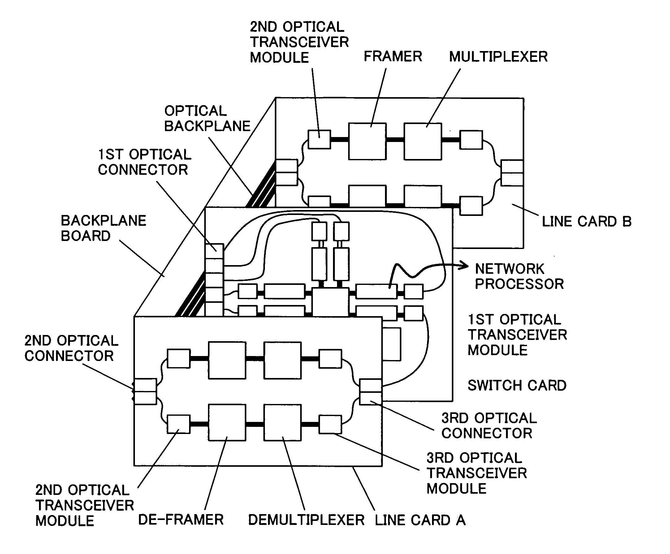
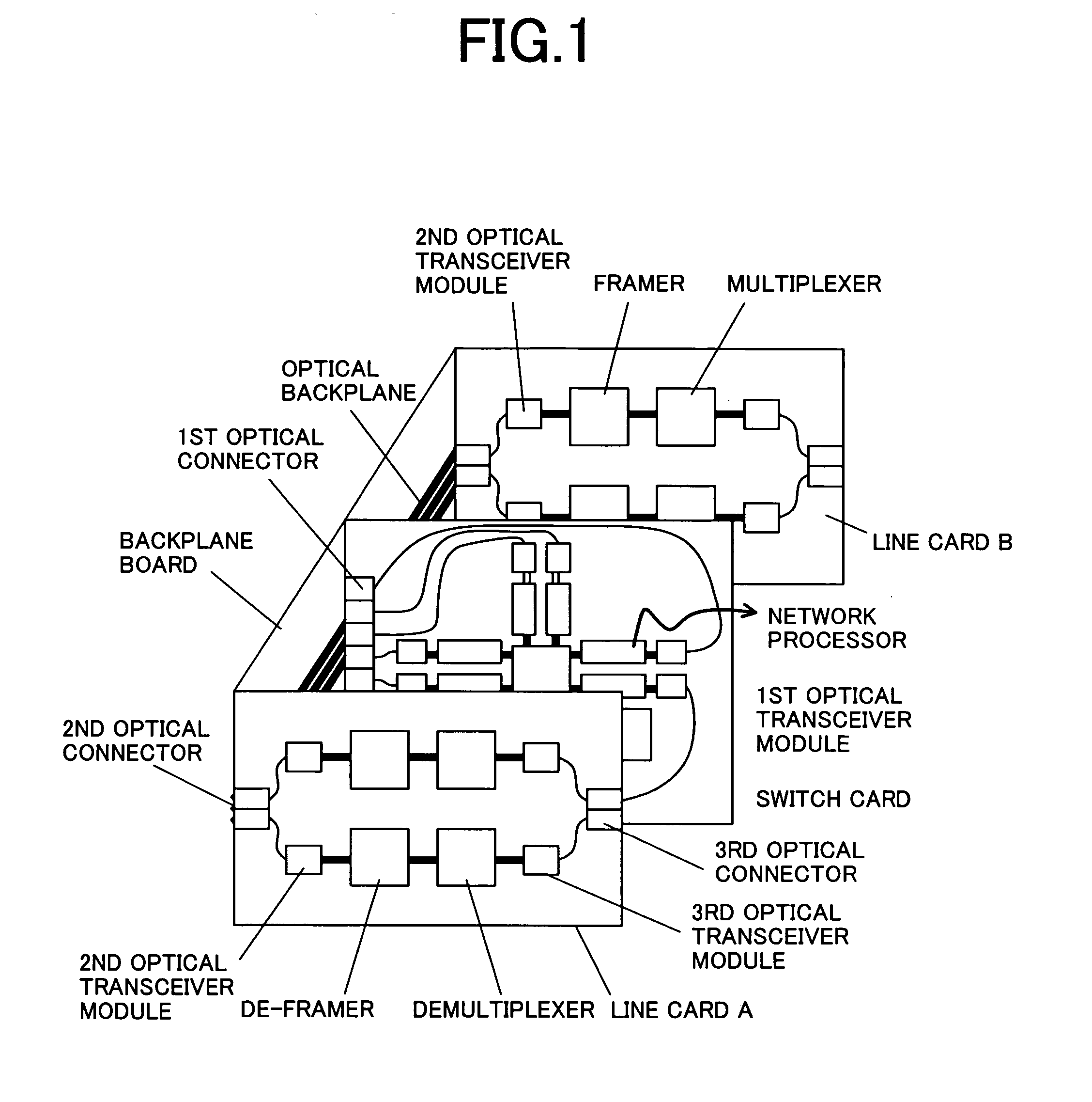
[0030] In the following embodiments, a plurality of line cards and one switch card are used to configure a network router / switch. And, an optical back plane board is used for the connection between each line card and the back plane board. FIG. 1 shows a packet switching system that includes two line cards A and B structured identically are connected to the switch card. The mounted parts are the same between the line cards A and B. The switch card uses an optical back plane board. In addition, the packet switching system in this embodiment is expected to be connected to WDM optical signal lines and the line cards A and B are provided with a WDM communication int...

second embodiment

[0048]FIG. 8 shows a packet switching system configured by connecting the line-cards and the switch cards in the fat tree structure shown in FIG. 6. The system has 16 inputs and 16 outputs. FIG. 8 shows a top view of the optical back plane board shown in FIG. 9; the top view is seen from a direction for inserting the cards in the board. The large four rectangles are switch-card-to-backplane optical connectors to which the switch cards are connected and the eight small rectangles are line-card-to-backplane optical connectors to which line cards are connected. Each thick solid line is an optical signal line between switch cards and each thin line is an optical signal line between a line card and a switch. One line card includes two link circuits. One switch card includes one switch consisting of 8 inputs and 8 outputs. The network topology is the star-type one. The back plane board employs this star-type line structure that uses optical signal lines. Four channel optical signal lines ...

third embodiment

[0050] Just like the first embodiment, in the packet switching system shown in this third embodiment, network processors, a switch, and back plane communication optical transceiver devices are disposed on the same board. Although the network processors and the switch are disposed in different packages separately in the first embodiment (multi-chip packaging), those are disposed in the same package as shown in FIG. 12. In this third embodiment, the optical transceiver devices are disposed in a different package and all those packages are disposed around the package in which the switch and the network processors are mounted. Because of such a multi-chip packaging, each package is reduced in volume and the line distance between the packages is reduced, thereby the loss of the transmission signals to increase in accordance with an increase of the frequencies is suppressed.

[0051] Furthermore, because the network processors and the switch are disposed in the same package, the line distan...


PUM


Abstract

Disclosed here is a BP type architecture packet switching system that prevents delay of packet forwarding in the system itself while keeping the system configuration flexibility. Furthermore, an optical BP can be used to reduce both of the number of optical signal line parts and the manufacturing cost. In the packet switching system, a back plane (BP) board is used between a network processor and a link circuit, not between a switch and a network processor when connection is established among a switch, a network processor, and a link circuit.

Description

CLAIM OF PRIORITY [0001] The present invention claims priority from Japanese application JP 2003-380631 filed on Nov. 11, 2003, the content of which is hereby incorporated by reference into this application. FIELD OF THE INVENTION [0002] The present invention relates to an internal structure for routers and switches used for computer networks and more particularly to a packet switching system to be connected to optical signal paths. BACKGROUND OF THE INVENTION [0003] Packet switching systems used for communications through computer networks have been used widely in various markets. They are referred to as routers and switches separately in their application fields. Network traffics are now expanding year by year along with the widespread of such broadband connections as ADSL, FTTH, etc. And, along with the widespread, the markets have come to require packet switching systems enabled for faster forwarding processes of received packets. [0004] Each conventional packet switching system...

Claims


Application Information

Patent Timeline
IPC IPC(8): H04L12/70
CPCH04L49/40H04B10/801
Inventor NISHIMURA, SHINJI
Owner HITACHI LTD
Why Eureka
Try Eureka