Bookbinding machine and prebinding apparatus
a pre-binding machine and pre-binding technology, applied in the field of bookbinding, can solve the problems of reducing efficiency, reducing the processing speed, and cracking at the folded portion, and achieve the effect of improving the bookbinding efficiency and shortening the processing time for bookbinding
- Summary
- Abstract
- Description
- Claims
- Application Information
AI Technical Summary
Benefits of technology
Problems solved by technology
Method used
Image
Examples
first embodiment
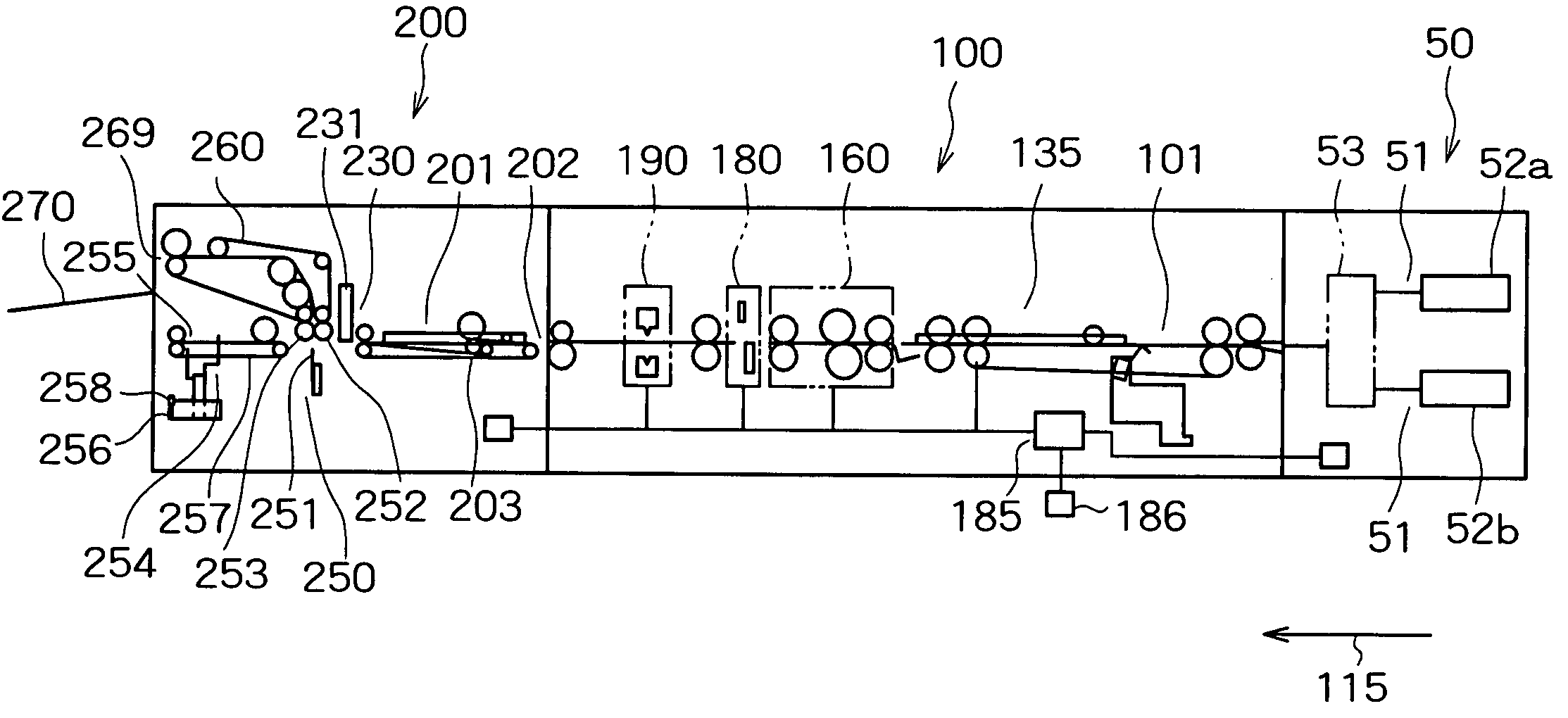
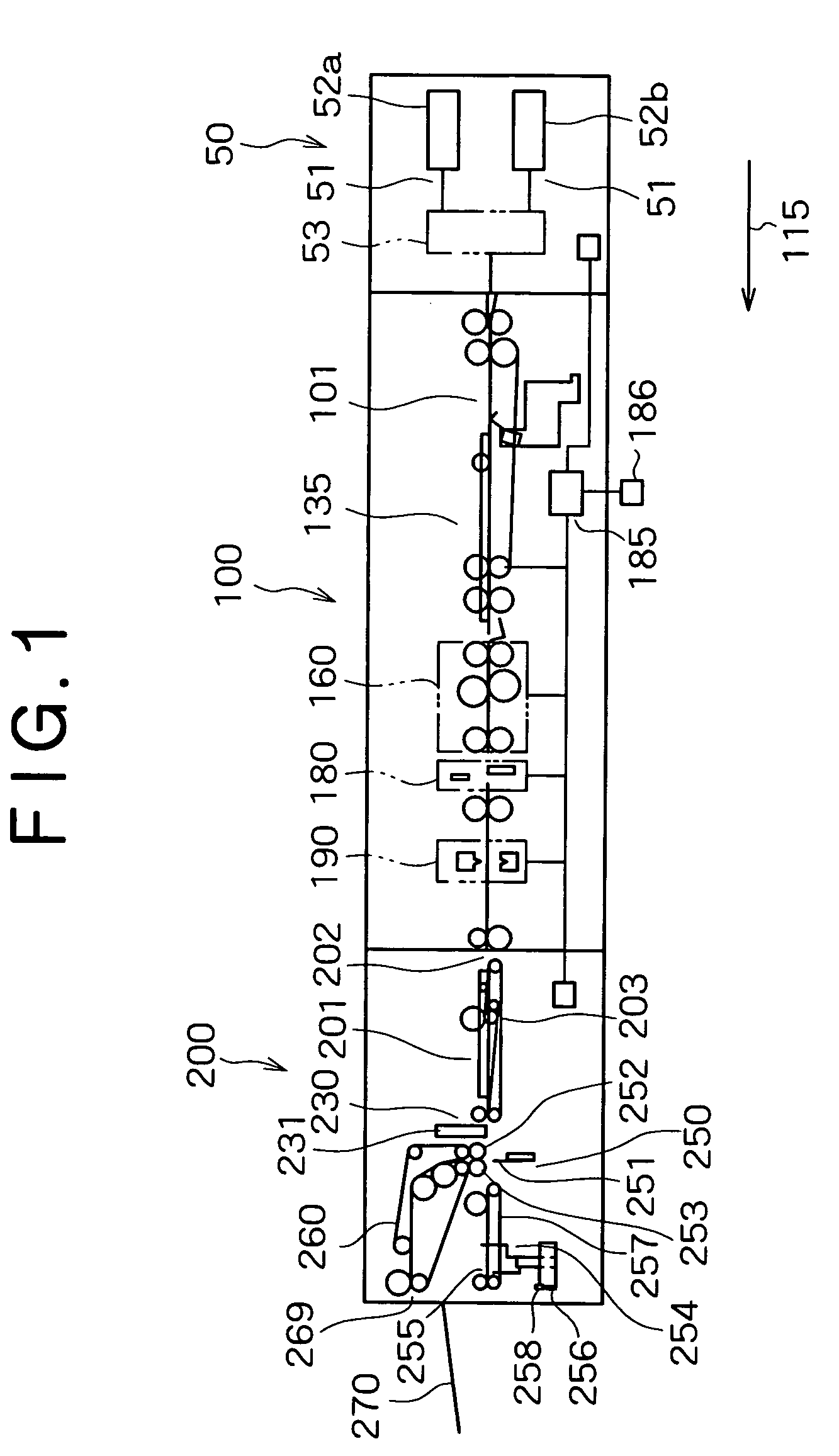
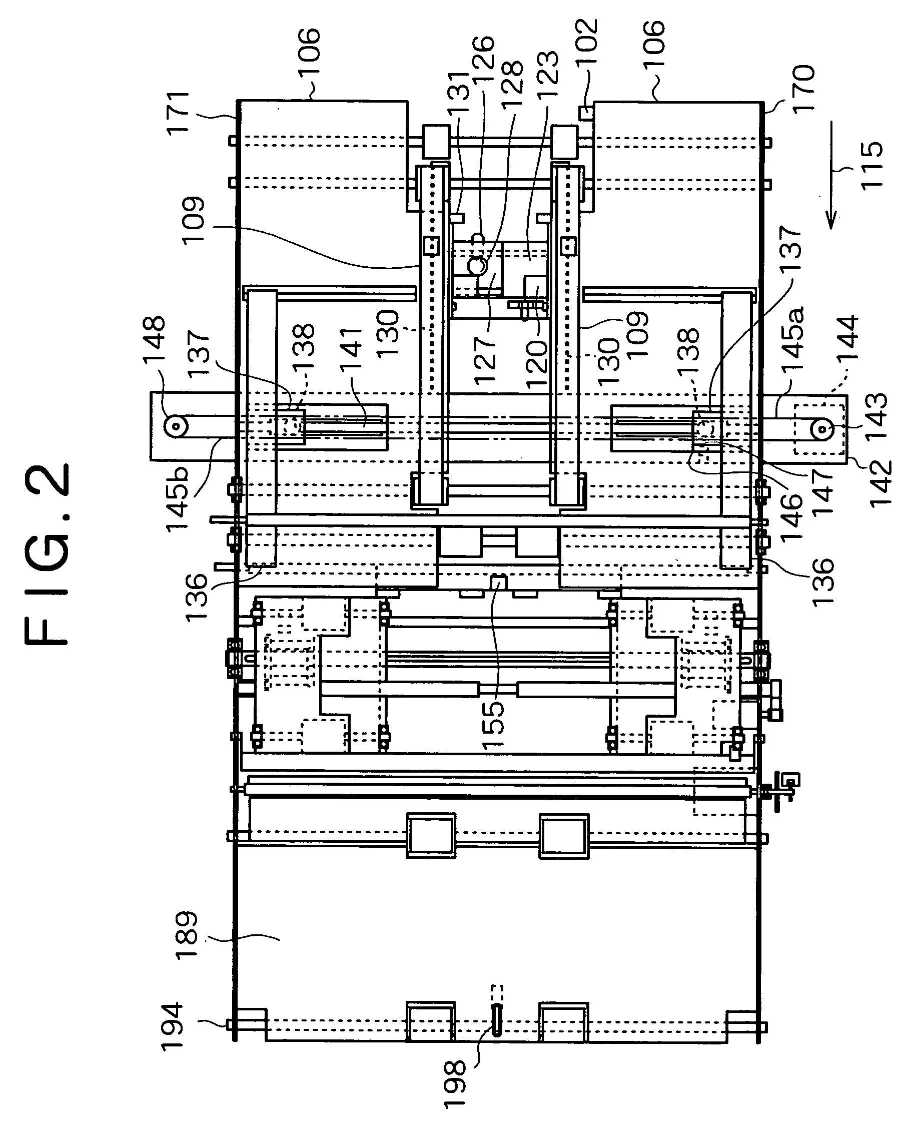
[0053] Preferred embodiments of the invention will be described below with reference to the accompanying drawings. To begin with, the present invention will be described. FIG. 1 is a side view illustrating a bookbinding machine according to the embodiment, FIG. 2 is a plan view illustrating a prebinding apparatus in the bookbinding machine shown in FIG. 1, FIG. 3 is a side view showing the neighborhood around the prebinding apparatus, FIG. 4 is a side view showing the neighborhood around the side portion of the prebinding apparatus, FIG. 5 is a side view showing a sheet-rear-end aligning device of the prebinding apparatus, and FIG. 6 is a side view showing a conveyance drive mechanism section of the prebinding apparatus. The bookbinding machine according to the embodiment binds a booklet formed of monochromatically printed pages and colored pages printed in color. The monochromatically printed pages are formed thin sheets of paper and each has margins at the peripheral portion, and ...
third embodiment
[0105] the invention will be described below. FIGS. 19A and 19B, FIGS. 20A and 20B, FIGS. 21A and 21B and FIG. 22 are diagrams showing the first operation pattern according to the embodiment step by step, and FIGS. 23A and 23B, FIGS. 24A and 24B, FIGS. 25A and 25B and FIGS. 26A and 26B are diagrams showing the second operation pattern according to the embodiment step by step. As shown in FIG. 19A, in the embodiment, the sheet feeder is provided with two sheet feeding shelves 52a and 52b and two sheet discharge ports which are directly connected to the respective sheet feeding shelves. A prebinding apparatus is provided with two sheet feed ports, which correspond to the sheet feeding shelves of the sheet feeder and are connected to the respective sheet feeding shelves of the sheet feeder. The sheet feed port of the prebinding apparatus which is connected to the sheet feeding shelf 52a of the sheet feeder is connected to the bypass path 310, and the sheet feed port of the prebinding a...
fourth embodiment
[0122] the invention will be described below. FIGS. 27A and 27B, FIGS. 28A and 28B, FIGS. 29A and 29B, FIGS. 30A and 30B, and FIG. 31 are diagrams showing the operation pattern according to the embodiment step by step. As shown in FIG. 27A, a changeover feeding path 321 for feeding sheets of paper to the feeding path 110 from the sheet feeding shelf 52a and a changeover feeding path 322 for feeding sheets of paper to the bypass path 310 from the sheet feeding shelf 52b are provided in the embodiment. This structure can allow an arbitrary combination of the sheet feeding shelves and the feeding paths to be selected. That is, sheets of paper can be supplied to the bypass path 310 and also to the feeding path 110 from the sheet feeding shelf 52a. Likewise, sheets of paper can be supplied to the feeding path 110 and also to the bypass path 310 from the sheet feeding shelf 52b.
[0123] In the operation pattern shown in FIGS. 27 to 31, color print sheets 22 are supplied to the sheet feedin...
PUM
| Property | Measurement | Unit |
|---|---|---|
| time | aaaaa | aaaaa |
| size | aaaaa | aaaaa |
| thick | aaaaa | aaaaa |
Abstract
Description
Claims
Application Information
 - R&D
- Intellectual Property
- Life Sciences
- Materials
- Tech Scout
- Unparalleled Data Quality
- Higher Quality Content
- 60% Fewer Hallucinations
Browse by: Latest US Patents, China's latest patents, Technical Efficacy Thesaurus, Application Domain, Technology Topic, Popular Technical Reports.
© 2025 PatSnap. All rights reserved.Legal|Privacy policy|Modern Slavery Act Transparency Statement|Sitemap|About US| Contact US: help@patsnap.com


