Exhaust gas muffler

a technology of exhaust gas muffler and muffler body, which is applied in the direction of exhaust treatment, engine components, mechanical equipment, etc., can solve the problems of high exhaust temperature, potential safety hazards, and muffler wear, and achieve the effect of reducing the risk of muffler damage, and reducing the safety of users

Inactive Publication Date: 2005-05-19
KLAUS FREDERICK NOWAK ADVANCED CAR SPECIALTIES
View PDF37 Cites 14 Cited by
  • Summary
  • Abstract
  • Description
  • Claims
  • Application Information

AI Technical Summary

Benefits of technology

[0008] Preferably, the operating temperature inside the muffler will be reduced, so that the muffler components are subjected to less heat stress and thereby achieve enhanced durability. The temperature of the exhaust gas output from the muffler will preferably also be reduced, producing a corresponding reduction in the risk of ignition of foreign materials and of back firing. It would be preferable as well if a heat shield or other bulky external device is not required, so that the muffler may be made as small as possible and thus more easily integrated into the existing motor compartments of the various internal combustion engine vehicles and devices.

Problems solved by technology

The exhaust gases from an internal combustion engine can be very hot, for example, over 1000° F. Such high temperatures can affect muffler components, in particular causing mufflers to wear out and require replacement faster than otherwise.
Another problem is that the high exhaust temperature may cause“after bang” or “back firing” when unburnt or semi-burnt hydrocarbons, which may be contained in the flow are ignited upon contact with hot muffler components.
High exhaust temperatures therefore are a potential safety hazard.
Also, since the motor compartment in smaller vehicles is more crowded, the heat emanating from a very hot muffler is more likely to have an adverse affect on the performance or durability of neighbouring components.
Thus, problems of high temperature exhaust gases can be more acute in smaller vehicles and motors.
As such, the muffler, if it gets very hot, becomes a safety hazard to users of the motorized device.
However, the outer insulation in this type of muffler also magnifies the problem of high internal and tailpipe exit temperature for the exhaust gases.
While these devices produce some cooling, the effect is limited since the cool air only passes past the outer skin of the muffler.
Further, the external heat shield adds bulk to the muffler, which can be a problem particularly in smaller vehicles where the space is not available.
This may force a costly redesign of the motor compartment and lead to a larger overall device.
Also the external heat shield adds weight and expense to the muffler, and is not that easy to fabricate.
Accordingly, in the absence of a more effective solution the durability and safety problems inherent to mufflers operating with high temperature exhaust are likely to continue.

Method used


Image

  • Exhaust gas muffler
  • Exhaust gas muffler
  • Exhaust gas muffler

Examples


Embodiment Construction

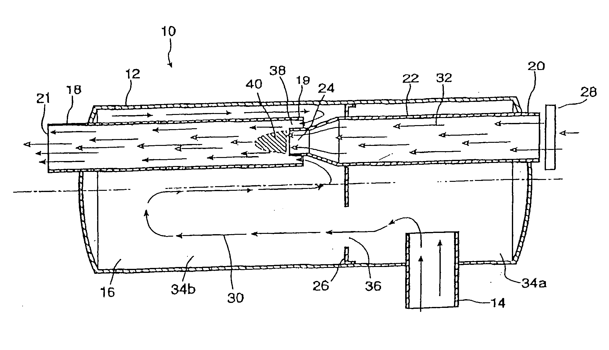
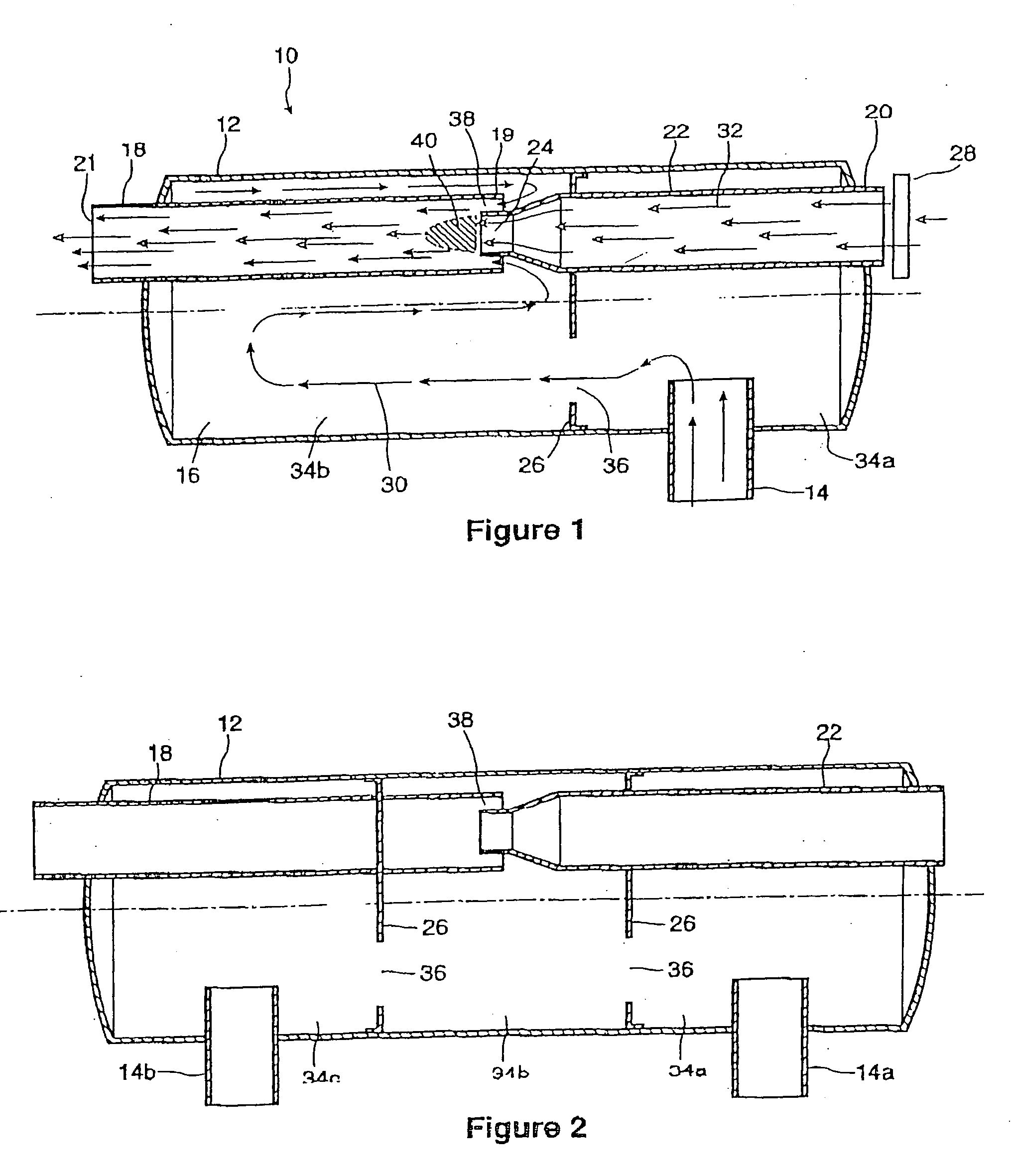
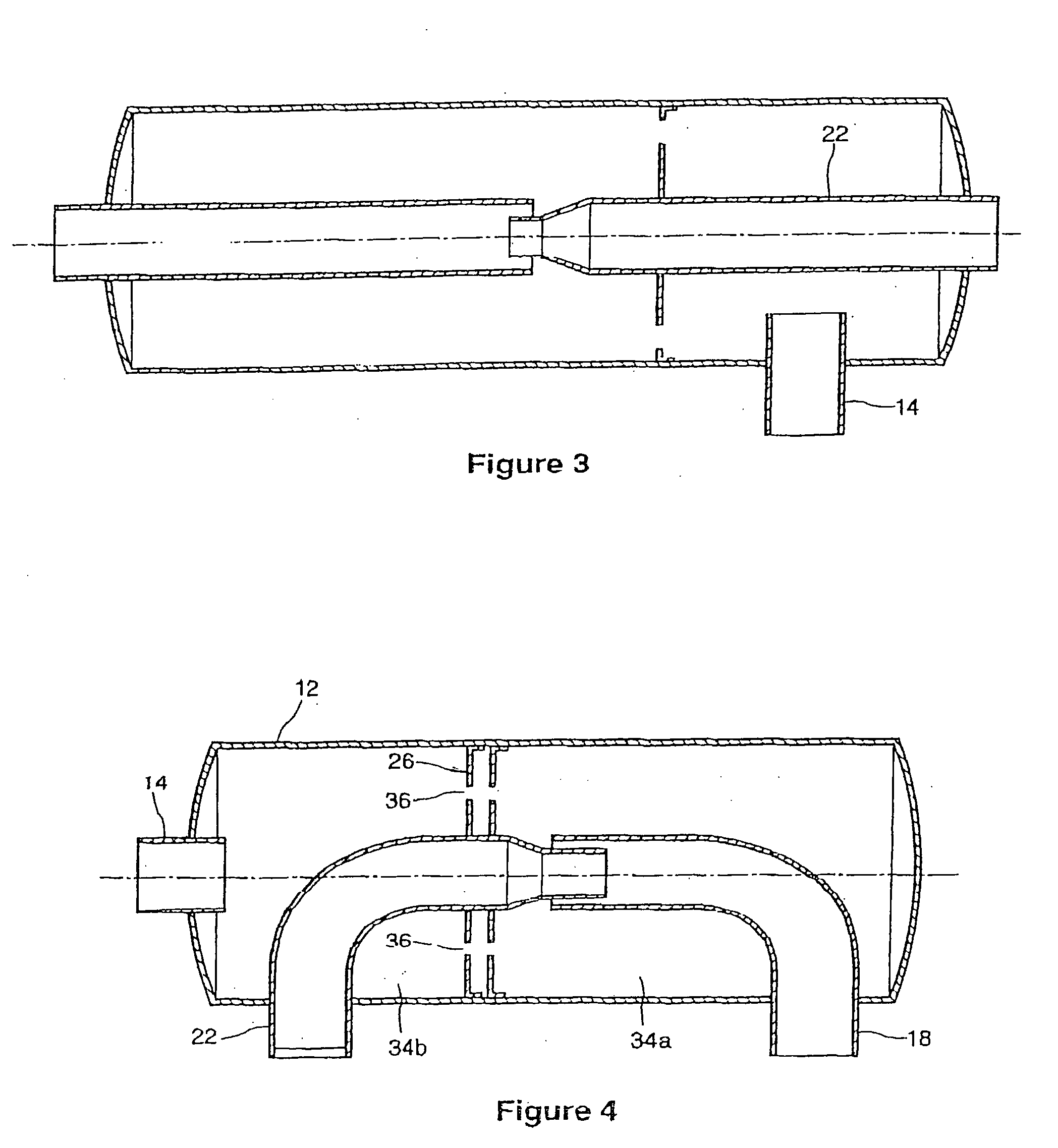
[0024] The exhaust muffler of the present invention is shown in a side cross-sectional view in FIG. 1 and generally designated as 10. The exhaust muffler 10 generally comprises a body 12, at least one inlet 14, a baffled chamber 16, at least one exhaust gas outlet or tailpipe 18, at least one fresh-air inlet 20 on the body12, a heat exchange conduit 22, and a fresh-air outlet 24. The baffled chamber 16 includes at least one baffle 26, and the fresh-air inlet 20 usually includes an air filter 28. The tailpipe 18 has an input end 19 inside the baffled chamber 16 and an output end 21 located outside the muffler 10.

[0025] The exhaust muffler 10 receives exhaust gas 30 through the inlet 14 and ambient air 32 through the fresh-air inlet 20. The exhaust gas 30 and ambient air 32 are shown as a series of arrows indicating the general flow of the gas and air through the device 10. For additional clarity and to distinguish the two gases, the exhaust gas 30 is represented by an open arrowhead...


PUM


Abstract

An exhaust gas muffler for an engine, the exhaust gas muffler having a body, at least one inlet for the exhaust gas from the engine on the body, a baffled chamber in the body to receive exhaust gas from the at least one exhaust gas inlet, at least one exhaust gas outlet from the baffled chamber to vent the exhaust gas from the baffled chamber, at least one fresh-air inlet on the body, a heat exchange conduit extending into the baffled chamber between the fresh air inlet and the at least one exhaust gas outlet, the heat exchange conduit being sized and shaped to permit heat exchange between the fresh air and the exhaust gas in the baffled chamber, and a fresh air outlet on the heat exchange conduit, the fresh air outlet being sized, shaped and located relative to the exhaust gas outlet to permit the fresh air to mix with exhaust gases being vented from the baffled chamber to lower an exit temperature of the exhaust gases.

Description

FIELD OF THE INVENTION [0001] This invention relates to the general field of exhaust systems, and more particularly to mufflers used with internal combustion engines. BACKGROUND OF THE INVENTION [0002] Internal combustion engines generate by products of combustion often referred to as exhaust gases. Typically, for noise control the exhaust gases pass through a muffler and tailpipe before being released. Such engines and their associated exhaust systems are ubiquitous, being used to power all types of motor vehicles as well as smaller, more specialized vehicles and devices such as, for example, golf carts, ATV's, lawn tractors, power generators, and other turf and industrial equipment. [0003] The exhaust gases from an internal combustion engine can be very hot, for example, over 1000° F. Such high temperatures can affect muffler components, in particular causing mufflers to wear out and require replacement faster than otherwise. Another problem is that the high exhaust temperature ma...

Claims


Application Information

Patent Timeline
Patent Type & Authority Applications(United States)
IPC IPC(8): F01N1/08F01N3/05F01N3/30F01N3/32F01N3/34F01N13/14
CPCF01N1/089Y02T10/20F01N3/303F01N3/32F01N3/34F01N13/14F01N2240/02F01N2240/20F01N2260/022F01N2450/22F01N2450/24F01N2450/30F01N2470/16F01N2470/18F01N2470/20F01N2470/30F01N2490/08F01N2490/16F01N2490/18F01N2530/02F01N2530/04F01N2530/26F01N3/05Y02T10/12
Inventor CROMBEEN, PETER F.
Owner KLAUS FREDERICK NOWAK ADVANCED CAR SPECIALTIES
Why Eureka
Try Eureka