Positional blasting system

a technology of positioning blasting and blasting cartridges, which is applied in the direction of blasting cartridges, weapons, weapon components, etc., can solve the problems of team of technicians, easy for even seasoned technicians to become temporarily disoriented in the field, and the task may be further complicated

Active Publication Date: 2005-05-19
DAVEY BICKFORD USA
View PDF35 Cites 103 Cited by
  • Summary
  • Abstract
  • Description
  • Claims
  • Application Information

AI Technical Summary

Benefits of technology

[0013] The present invention achieves these and other objectives via a blasting system that utilizes a handheld programming unit to locally program a plurality of detonators located in a plurality of boreholes at a blasting site, wherein the handheld programming unit automatically uses positional movement data of the unit itself in order to determine the firing delay times for the detonators. For instance, the programming unit may download a firing delay ti...

Problems solved by technology

Consequently, it is easy for even a seasoned team of technicians to become temporarily disoriented in the field, often requiring them to backtrack and/or to re-do their work.
Additionally, the difficulties associated with this conventional practice can frustrate a team of technicians in a blasting operation, and this can create a dangerous situation.
This task may be further complicated in situations when the technicians...

Method used


Image

  • Positional blasting system
  • Positional blasting system
  • Positional blasting system

Examples


Embodiment Construction

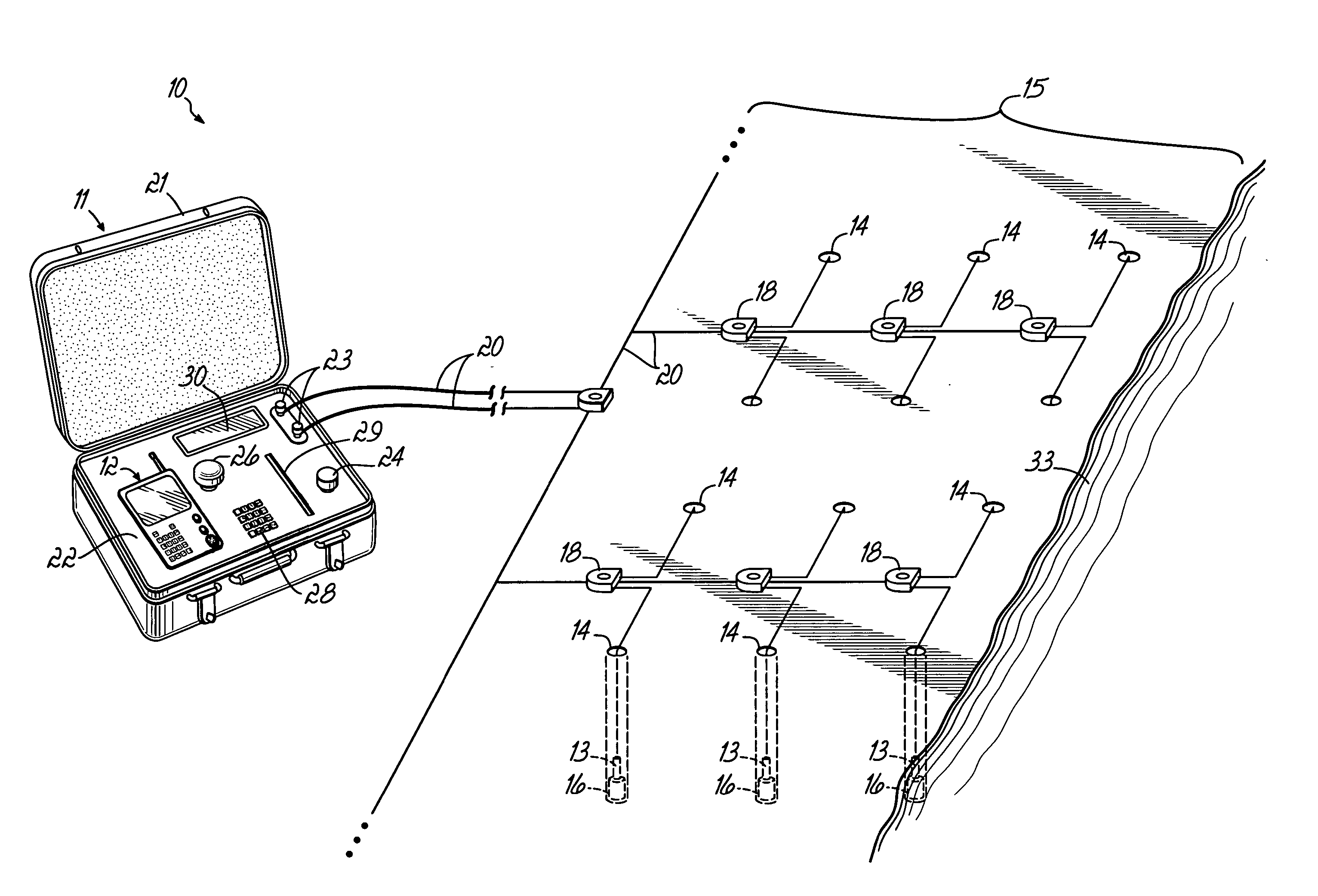
[0032]FIG. 1 shows a position-based blasting system 10 in accordance a preferred embodiment of the present invention. Generally, the system 10 includes a master controller 11, a handheld programming unit 12 and a plurality of programmable detonators 13 that are located in respective boreholes 14 at a blasting site 15. Each detonator 13 is operatively associated with a number of explosive charges 16. Also, the detonators 13 operatively connect to the blasting machine 11 by connectors 18 and associated cabling 20. Preferably, the blasting machine 11 includes an outer case 21, a cradle 22, connecting terminals 23, a firing switch 24, a charging switch 26, a keypad or other data entry device 28, a disc drive 29, a display 30 and an internal processor (not shown).

[0033] The detonators 13 are conventionally programmable detonators capable of receiving blasting information that includes a delay time. The delay time is used for decrementing from a firing signal to a desired blasting time. ...


PUM


Abstract

A blasting system facilitates the actuation of a plurality of programmable detonators according to a desired blasting pattern, to cause the discharge of a plurality of associated charges, by downloading to the detonators blasting information that can be automatically determined by a portable handheld unit that incorporates a positional detecting device, such as a GPS device. The blasting information for any given detonator can be determined by the handheld unit as a function of the distance and the direction of the movement of the unit to the detonator, and/or by the actual GPS location while at the site of the detonator. This automatic determination of blasting information, and particularly the delay times, based on the movement of the unit to the detonator, eliminates error prone human calculations of the delay times needed for multiple detonators at a blasting site. This simplifies the operations and procedures needed for achieving a desired blasting pattern, without sacrificing safety or quality.

Description

FIELD OF THE INVENTION [0001] The present invention relates to blasting systems, and more particularly to a blasting system that controls a plurality of detonators to cause a desired blasting sequence, for applications such as mining. BACKGROUND OF THE INVENTION [0002] Conventional blasting systems rely on a plurality of detonators to controllably fire a complement of associated charges in a desired blasting sequence. The detonators and charges are typically arranged in a plurality of boreholes along and / or around the blasting site. The detonators are interconnected by electrically conductive cables that operatively connect to a blasting machine. In most systems, the blasting machine coordinates detonation of the charges by sending a firing signal to each detonator. Typically, at each detonator the firing signal initiates a countdown from a programmed delay time. A technician programs a desired delay time into each detonator. Generally, the charges then detonate when the counters of...

Claims


Application Information

Patent Timeline
IPC IPC(8): F42D1/055
CPCF42D1/055
Inventor MCCLURE, ROBERTTROUSSELLE, RAPHAEL
Owner DAVEY BICKFORD USA
Why Eureka
Try Eureka