Solar cell module and manufacturing method therefor

Inactive Publication Date: 2005-05-19
CANON KK
View PDF47 Cites 192 Cited by
  • Summary
  • Abstract
  • Description
  • Claims
  • Application Information

AI Technical Summary

Benefits of technology

[0011] The present invention has been made in view of the circumstances described above, and therefore an object of

Problems solved by technology

Although an aluminum alloy used for this frame is lightweight and superior in weather resistance and workability, it is expensive, which is a factor increasing the cost of the solar cell module.
However, when the thickness of the glass is increased as in the former method, this causes a reduction in light-transmissivity and a deterioration in power generation efficiency.
Moreover, this causes an increase in weight, which means it is necessary to enhance the strength of the support member itself.
Further, when tempered glass is used as in the latter method, this inevitably leads to an increase in cost.
However, when manufacturing a solar cell module, it is necessary to bond components such as the EVA, the solar cell, and the extruded aluminum material at a high temperature of about 150° C. Since the requisite strength of the module cannot be secured when the rigid plate material is planar, the

Method used


Image

  • Solar cell module and manufacturing method therefor
  • Solar cell module and manufacturing method therefor
  • Solar cell module and manufacturing method therefor

Examples


example 1

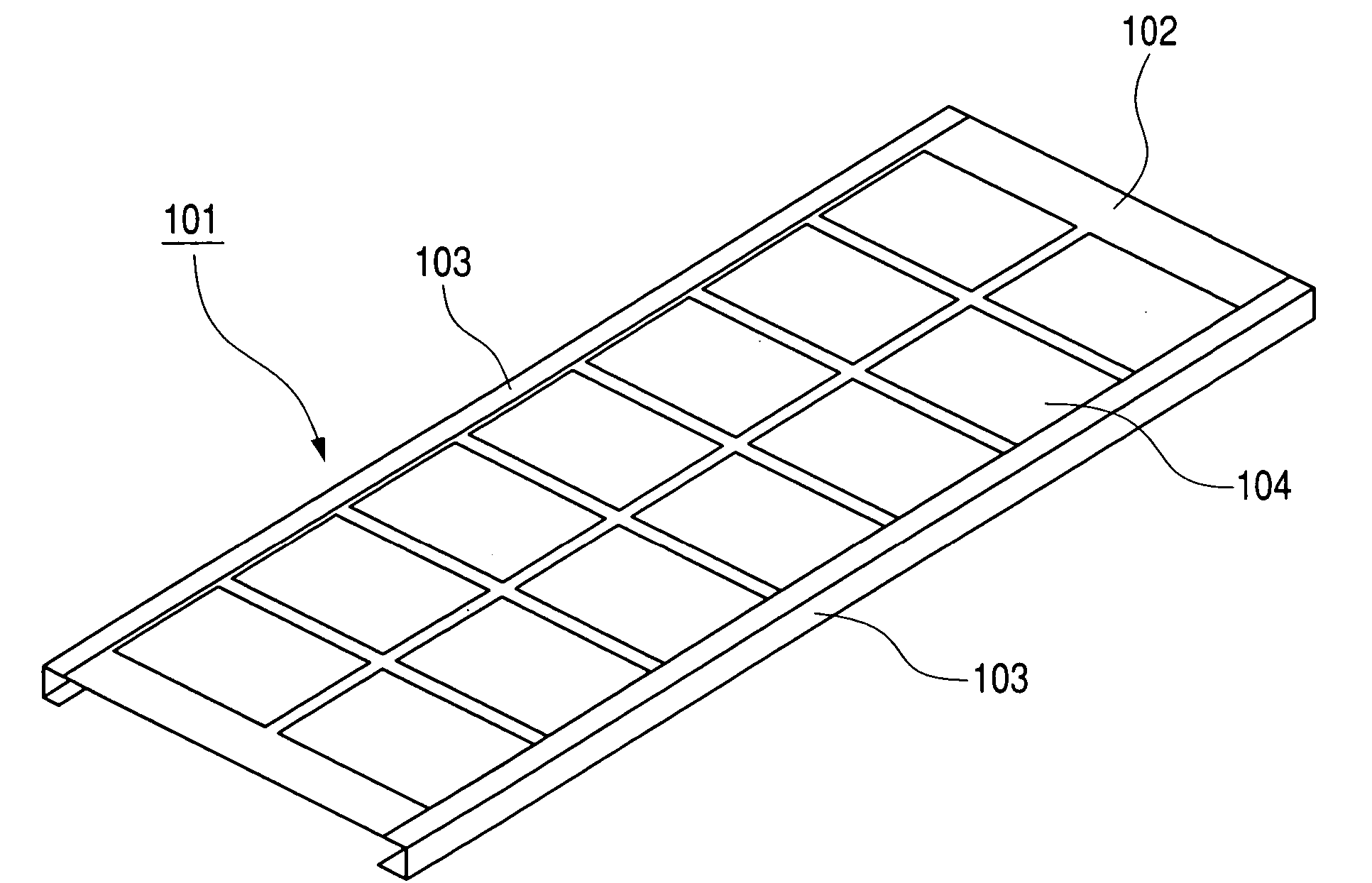
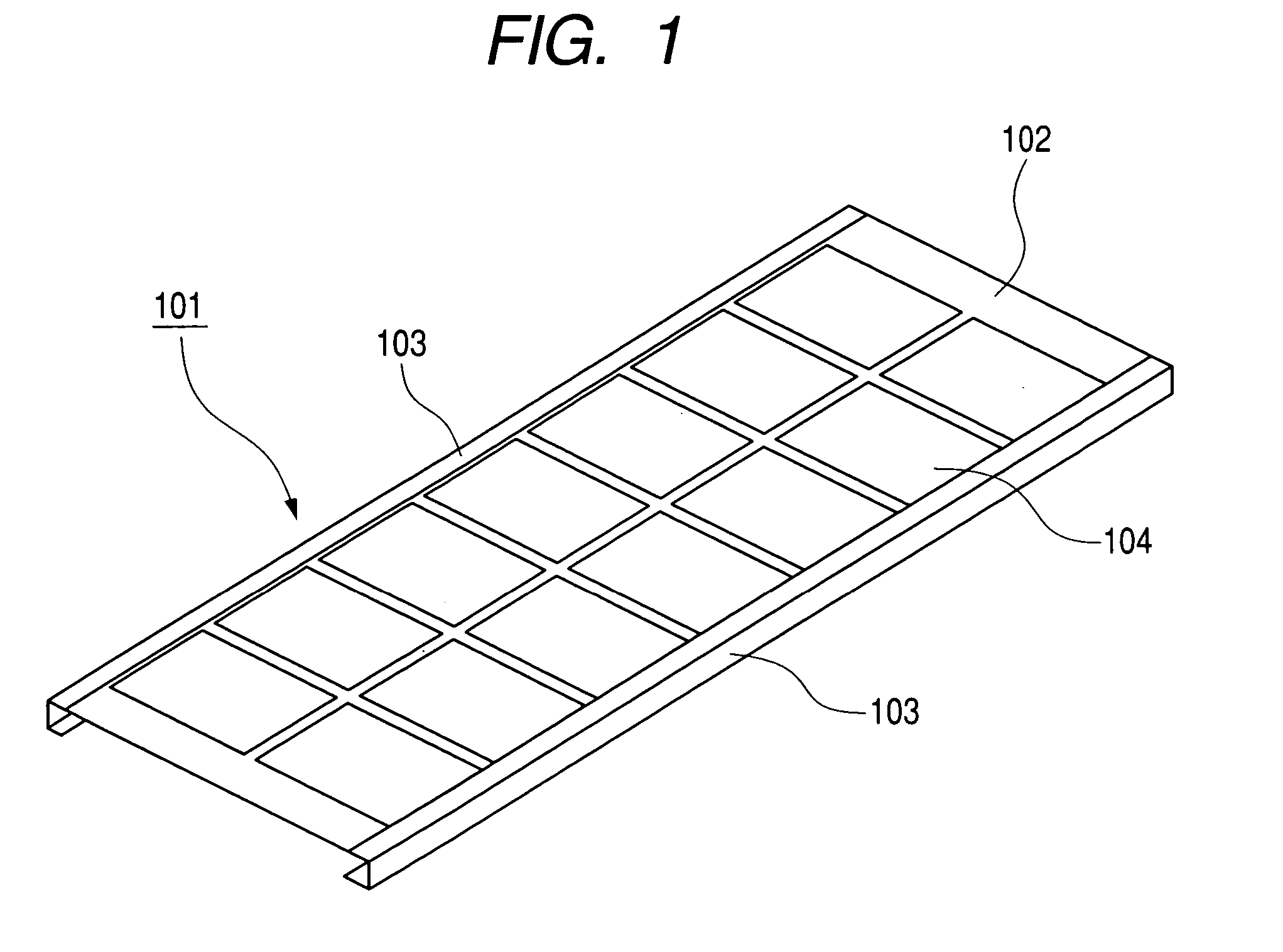
[0059] A solar cell module according to Example 1 of the present invention is composed of: a solar cell panel using an amorphous / microcrystalline silicon stacked solar cell that is covered with a covering material consisting of ETFE, EVA and PET, and integrally stacked with a molten Zn55%—AL-based alloy-plated steel plate (Galvalume steel plate); an aluminum frame; and a back member made of a Galvalume steel plate provided on the back side of the solar cell panel. The back member is composed of a joining portion for joining to the back side of the solar cell panel, and a projection portion extending in the direction crossing the aluminum frame. The aluminum frame has a first engaging portion for engaging with the solar cell panel and the joining portion of the back member, and a second engaging portion for engaging with the projection portion of the back member.

[0060]FIG. 4 is a schematic view of the solar cell module according to Example 1 as seen from its light-receiving surface ...

example 2

[0079] A solar cell module according to Example 2 of the present invention is composed of: a solar cell panel using a plurality of amorphous / microcrystalline silicon stacked solar cells covered with a covering material consisting of ETFE, EVA and PET; an aluminum frame; and a back member consisting of a molten Zn55%—Al-based alloy-plated steel plate provided on the back side of the solar cell panel and having a plurality of projection portions formed by bending.

[0080]FIG. 14 is a schematic view of the solar cell module according to Example 2 as seen from its light-receiving surface side. Reference numeral 1401 denotes a solar cell module, 1402 a solar cell panel, 1403 an aluminum frame, 1404 a bending portion of a back member, and 1405 an amorphous / microcrystalline silicon stacked solar cell.

[0081]FIG. 15 is a schematic diagram of the solar cell panel according to Example 2. Reference numeral 1501 denotes a solar cell panel, 1502 an amorphous / microcrystalline silicon stacked solar...

example 3

[0088] A solar cell module according to Example 3 of the present invention is composed of: a solar cell panel using a plurality of amorphous / microcrystalline silicon stacked solar cells covered with a covering material consisting of ETFE, EVA and PET; an aluminum frame; and a back member consisting of a coated zinc steel plate provided on the back side of the solar cell panel and having a plurality of projection portions formed by bending.

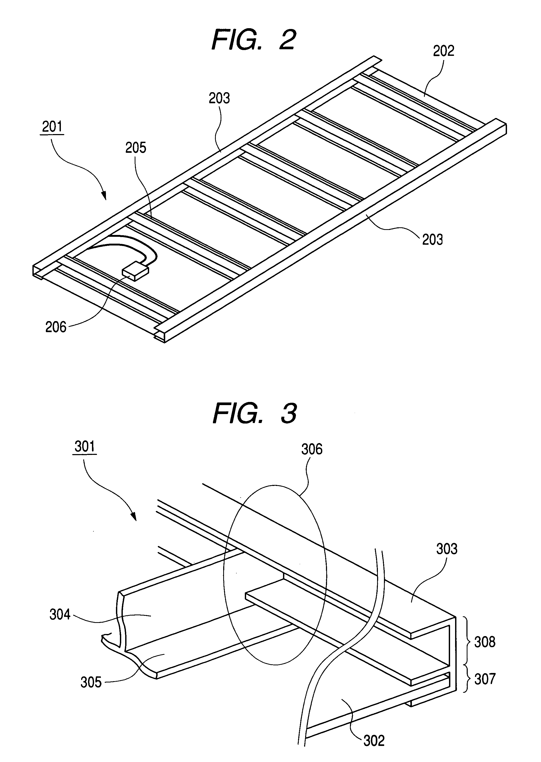
[0089]FIG. 19 is a schematic view of the solar cell module according to Example 3 as seen from its non-light-receiving surface side. Reference numeral 1901 denotes a solar cell module, 1902 a solar cell panel, 1903 a back member, 1904 a bending portion of the solar cell panel, and 1905 a junction box.

[0090]FIG. 20 is a schematic view showing the construction of the engaging portion of the back portion engaged with the aluminum frame according to Example 3. Reference numeral 2001 denotes a back member, 2002 a projection portion of the back member,...


PUM


Abstract

The solar cell module of the present invention includes a solar cell panel, a frame, and a back member provided on a back side of the solar cell panel, wherein the back member includes a joining portion for joining the back member to the back side of the solar cell panel, and a projection portion extending in a direction crossing the frame, and wherein the frame has a first engaging portion for engaging with the solar cell panel and the joining portion of the back member, and a second engaging portion for engaging with the projection portion of the back member, whereby the present invention provides a solar cell module having a high strength and a light weight at a low cost.

Description

BACKGROUND OF THE INVENTION [0001] 1. Field of the Invention [0002] The present invention relates to a solar cell module including a solar cell panel, a frame, and a back member having a projection portion, wherein the solar cell panel and the back member are engaged with the frame, thereby providing a solar cell module having a high strength and a light weight which is manufactured in a low cost. [0003] 2. Related Background Art [0004] Conventionally, many framed solar cell modules have been implemented as a photovoltaic power generating system which is installed on the roof of residential buildings to compensate for an electrical power supplied to the households. Often used as this type of the photovoltaic power generating system is one which employs a solar cell using a glass substrate and an aluminum frame provided as its frame member. Although an aluminum alloy used for this frame is lightweight and superior in weather resistance and workability, it is expensive, which is a fac...

Claims


Application Information

Patent Timeline
IPC IPC(8): H01L31/042H01L25/00H01L31/048
CPCY02B10/12Y02E10/50H01L31/02008H02S30/10H02S20/00H01L31/048H02S20/24H02S40/34Y02B10/10
Inventor MATSUSHITA, MASAAKIITOYAMA, SHIGENORIKATAOKA, ICHIROMUKAI, TAKAAKIMAKITA, HIDEHISA
Owner CANON KK
Why Eureka
Try Eureka