
Electrically operated actuator provided with rocking arm

a technology of electric actuator and rocking arm, which is applied in the direction of electrical equipment, mechanical energy handling, clamps, etc., can solve the problems of pneumatically operated actuators being extremely noisy, inducing overstress in the actuator, and increasing the cost and complexity of the same lines, so as to eliminate parasitic vibration and oscillation of the same work arm, and precise control of the position and movement of the work arm

Inactive Publication Date: 2005-05-19
UNIVER
View PDF2 Cites 4 Cited by
  • Summary
  • Abstract
  • Description
  • Claims
  • Application Information

AI Technical Summary

Benefits of technology

[0011] The main object of this invention is to provide an actuator provided with a rocking work arm, enabling a precise control of the position and of the movement of the work arm, eliminating parasitic vibrations and oscillations of the same work arm.
[0012] A further object of this invention is to provide an actuator of the aforementioned type, which is structurally simple and inexpensive, and which allows to limit the costs and complexity of the systems dedicated to its operation.
[0013] A still further object of this invention is to provide an actuator of the aforementioned type, which produces limited noise and no emissions of pollutant substances, thereby contributing to an improvement of the quality of the work environment.
[0014] Still another object of this invention is to provide an actuator of the aforementioned type, whereby it is possible to detect the position of the work arm under any operating condition, also in the event of accidental interruption of the power supply.

Problems solved by technology

The use of pneumatic control means however involves several functional problems, in that the use of a compressible fluid such as pressurised air does not allow a precise control of the position and the movement of the work arm, and in addition involves a possible onset of vibrations and oscillations of the same work arm, which induce overstress in the actuator.
Moreover, as regards plant problems, it is necessary to provide suitable production and distribution systems for the pressurised air to the different actuators installed along the assembling lines, with a consequent increase in the costs and complexity of the same lines.
A further problem is that pneumatically operated actuators are extremely noisy, especially during discharge of the air from the cylinder, and are liable to constitute a source of environmental pollution due also to atomisation into the atmosphere of the lubricants often contained in industrial pressurised air.
Furthermore, in general, conventional type actuators do not offer the possibility of simple and accurate adjustment and control of the work arm movement, in particular during the transient states of starting up and stopping, in that it is only possible to establish in advance the motion angle of the arm by means of complex mechanical operations for adjusting the actuators.
Another drawback of such actuators is that they can't be manually operated, causing some control end safety problems, in that, in case of faults of the control means, the supporting structure connected to the work arm control could result in a dangerous position, without any possibility of intervention.

Method used


Image

  • Electrically operated actuator provided with rocking arm
  • Electrically operated actuator provided with rocking arm
  • Electrically operated actuator provided with rocking arm

Examples


Embodiment Construction

[0035] The general features of this invention will be illustrated hereunder by means of a preferred embodiment.

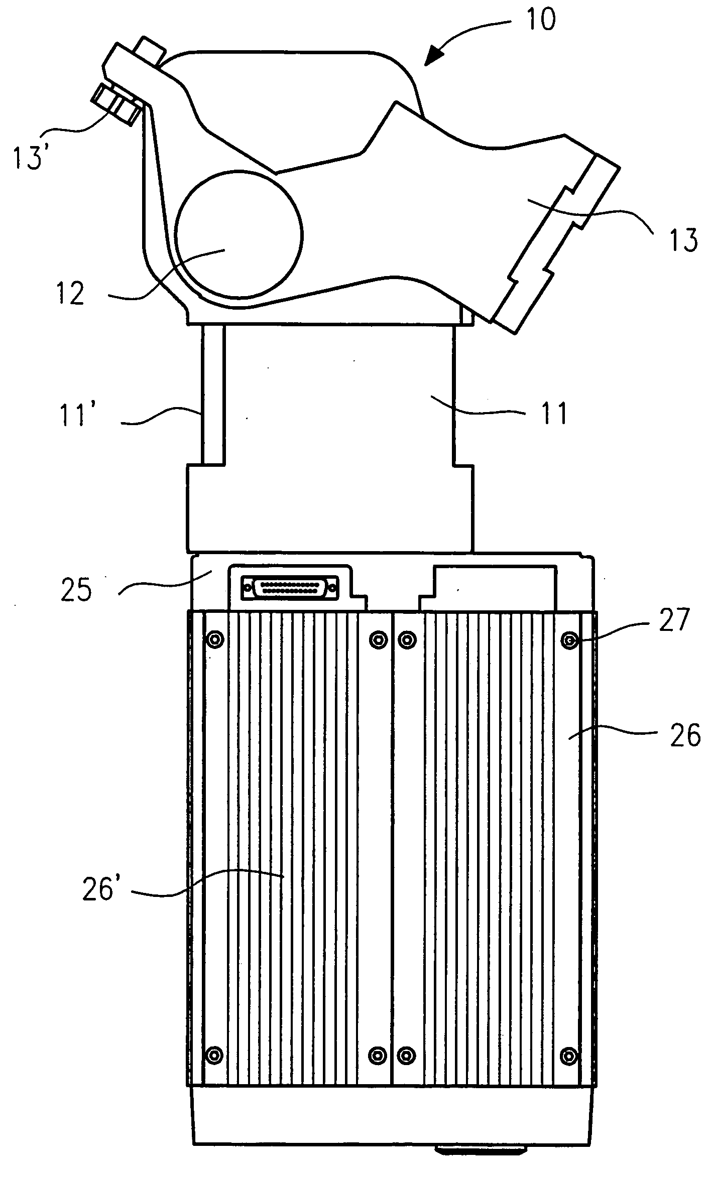
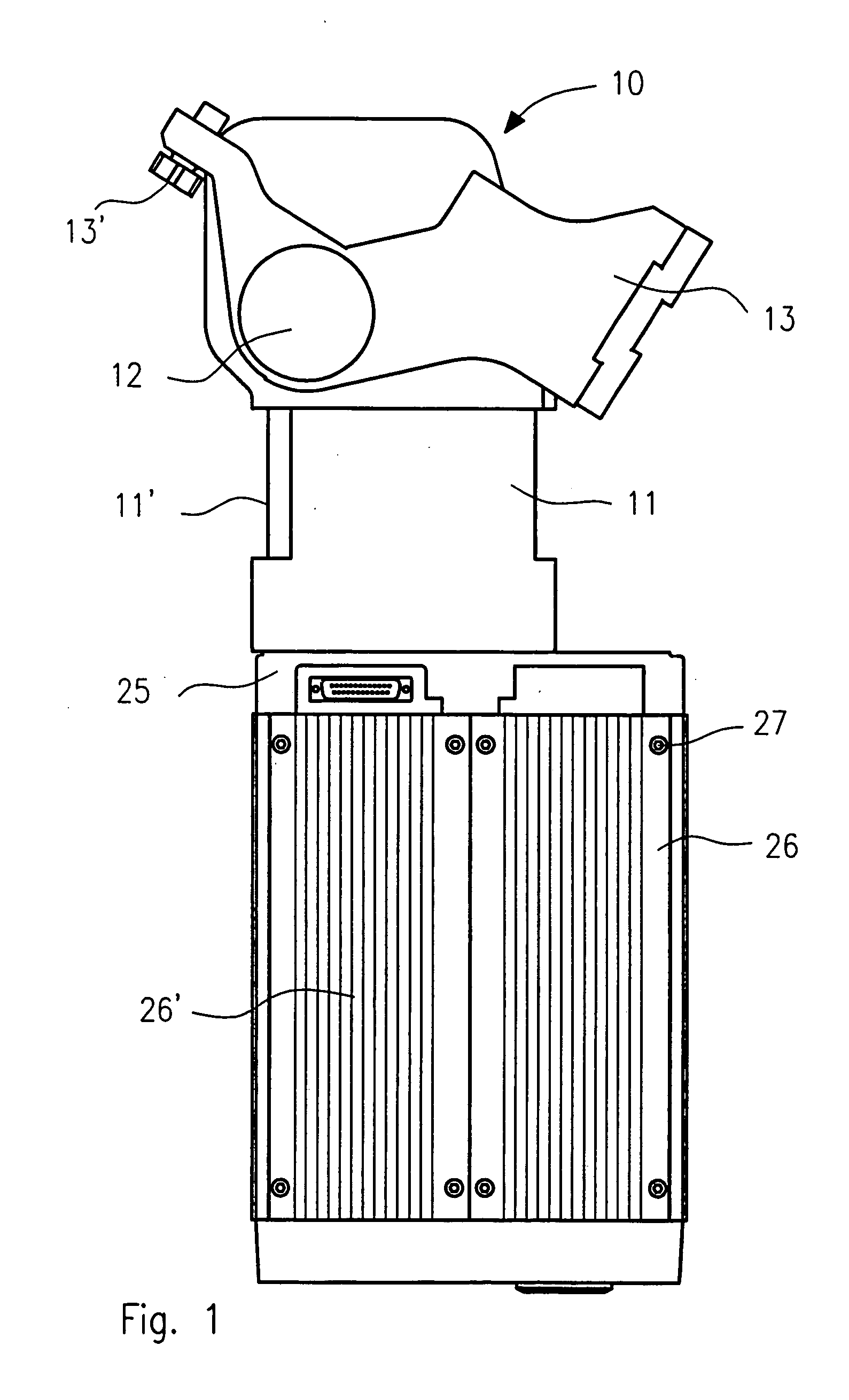
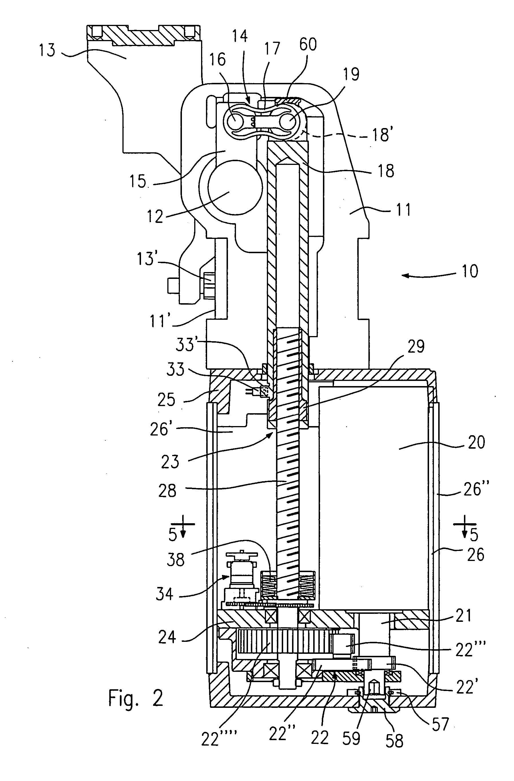
[0036] The FIGS. 1 to 7 show an electrically operated actuator having a rocking arm according to the invention, for operating an angularly movable supporting structure provided with a plurality of clamping and / or centering devices for workpieces.

[0037] In particular, as illustrated in FIGS. 2 and 3, the actuator, indicated as a whole by reference 10, comprises a box-shaped body 11, which supports, by a pivotal axis 12, at least one rocking arm 13 angularly movable between a first and a second operative position.

[0038] The actuator 10 also comprises linear control means operatively connected with the rocking arm 13 by means of a toggle-lever mechanism 14 housed in the box-shaped body 11.

[0039] The toggle-lever mechanism 14 in particular comprises a crank 15, pivotally connected to the axis 12 and movable in rotation with the rocking arm 13, the crank 15 being connected w...


PUM


Abstract

An electrically operated actuator includes a box-shaped body to which an angularly movable rocking arm is pivotally connected; the actuator also includes control elements operatively connected to the rocking arm by a toggle-lever mechanism, the control elements in turn having at least one electric motor, and a connecting screw-nut mechanism. The actuator further includes a position transducer device of rotary and absolute type, providing reference signals univocally related to the angular positions of the rocking arm, and a programmable electronic control unit and self-braking elements for the electric motor, the control unit being programmed to control the angular rotation of the rocking arm and to actuate the self-braking elements for the electric motor, in relation to the control signals provided by the absolute transducer device.

Description

BACKGROUND OF THE INVENTION [0001] This invention concerns an electrically operated actuator provided with a rocking work arm, used in particular in the manufacture of motor vehicles for operating angularly movable structures or handling equipments provided with a plurality of clamping and / or centering devices for clamping and / or centering work pieces or metal sheets of bodyworks to be assembled, or for other similar uses. STATE OF THE ART [0002] Pneumatic actuators having a rocking arm are commonly known, which are used for example in the automotive manufacturing field, along bodywork assembling lines, to move handling equipments or supporting structures for a plurality of clamping and / or centering devices. [0003] An actuator of this type, known for example from EP 1 300 625, generally comprises a box-shaped body to which a work arm is pivotally connected, said work arm being angularly movable between a first and a second operative position; the actuator further comprises linear dr...

Claims


Application Information

Patent Timeline
IPC IPC(8): B25B5/12
CPCB25B5/122B25B5/12
Inventor MIGLIORI, LUCIANO
Owner UNIVER
Learn More