Synchronous motor control device and method of correcting deviation in rotational position of synchronous motor

a technology of synchronous motor and control device, which is applied in the direction of motor/generator/converter stopper, electronic commutator, dynamo-electric converter control, etc., can solve the problems of inability to perform precise position correction, inability to accurately correct deviation in rotational position, and high cost of the apparatus to which this method is applied

Active Publication Date: 2005-05-19
MITSUBISHI ELECTRIC CORP
View PDF8 Cites 63 Cited by
  • Summary
  • Abstract
  • Description
  • Claims
  • Application Information

AI Technical Summary

Benefits of technology

[0014] Accordingly, it is possible to precisely correct a deviation in rotational position related to a rotational position detector even in a state in which a load is connected with a rotor without using an unloading detector and a motor voltage detector.

Problems solved by technology

Therefore, an apparatus to which this method is applied becomes expensive.
Therefore, in a state in which a load such as an internal combustion engine is connected with the rotor, there is a fear that the rotor stops at a position deviated from the predetermined position by the frictional force of the load, so that the deviation in rotational position cannot be precisely corrected.
Therefore, when the load is connected with the rotor, the precise position correction cannot be performed because of a variation in rotational rate resulting from the load.

Method used


Image

  • Synchronous motor control device and method of correcting deviation in rotational position of synchronous motor
  • Synchronous motor control device and method of correcting deviation in rotational position of synchronous motor
  • Synchronous motor control device and method of correcting deviation in rotational position of synchronous motor

Examples


embodiment 1

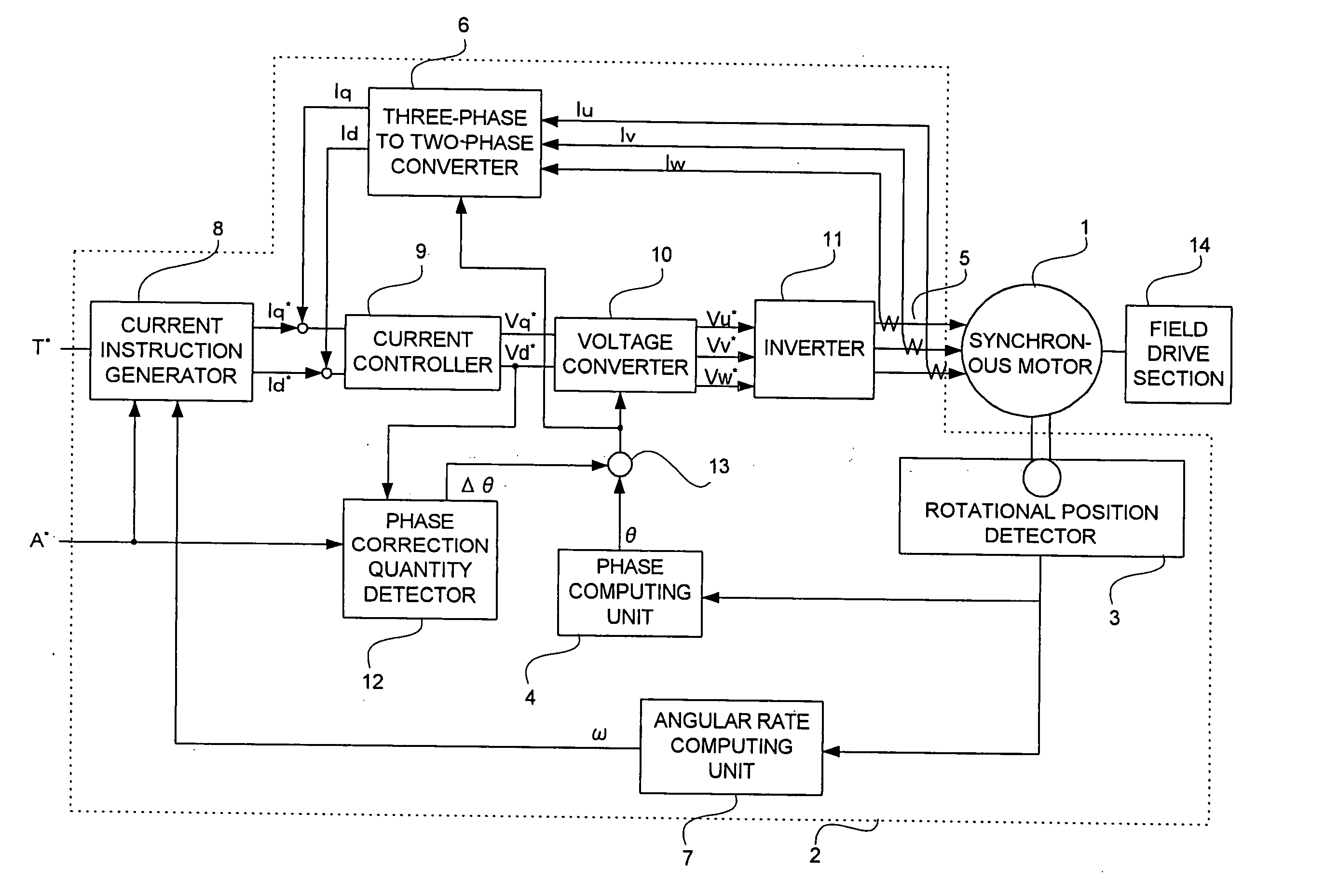
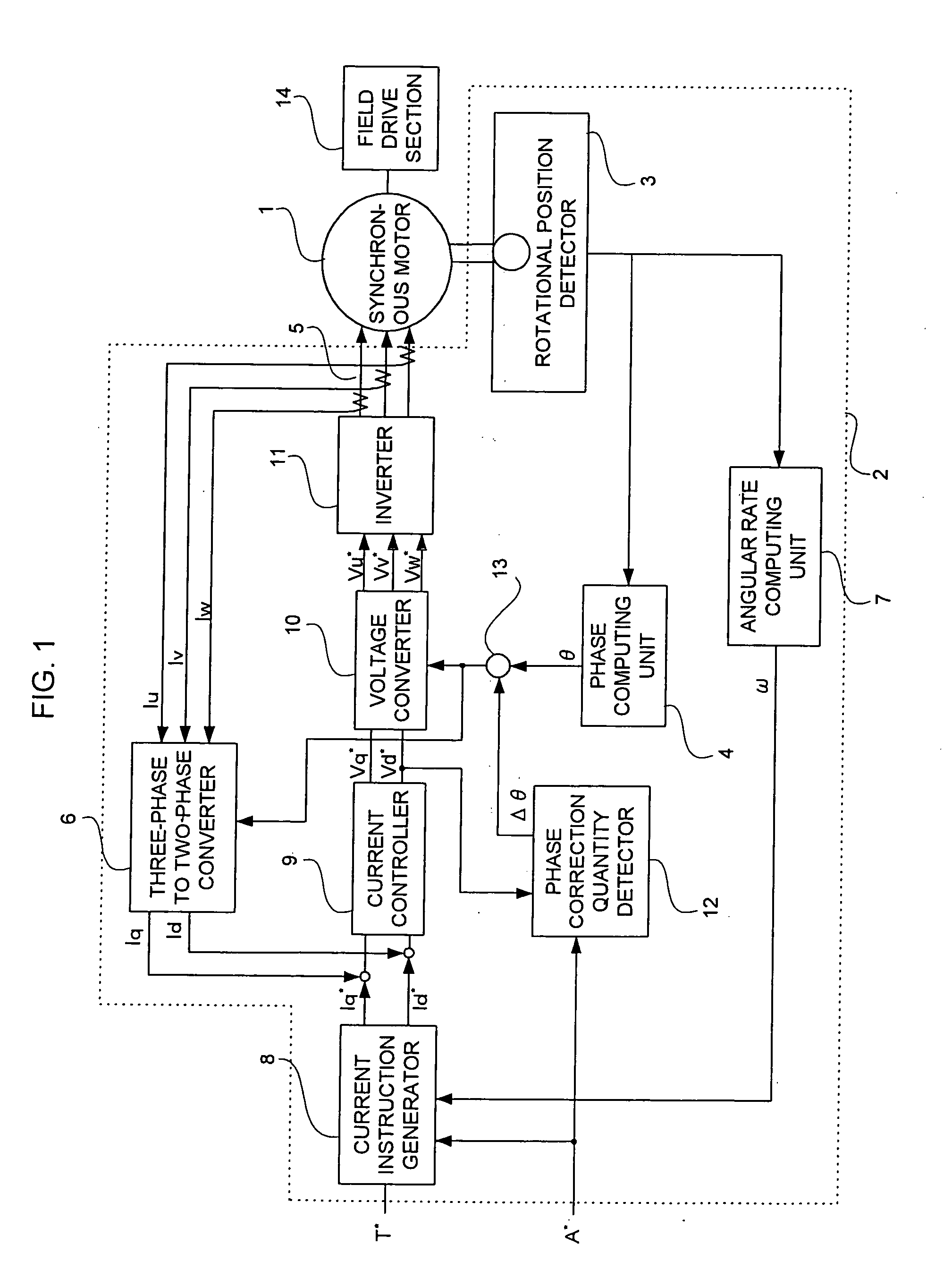
[0021]FIG. 1 is a block diagram showing a synchronous motor control device according to Embodiment 1 of the present invention.

[0022] The synchronous motor control device includes a synchronous motor 1 having a permanent magnet field or a winding field and a control device 2 for controlling a synchronous motor. The control device 2 includes: a rotational position detector 3 which is composed of a resolver and detects a rotor position of the synchronous motor 1; a phase computing unit 4 for computing a rotor positional angle θ from an output of the rotational position detector 3; a current detector 5 for detecting three-phase currents Iu, Iv, and Iw of the synchronous motor 1; a three-phase to two-phase converter 6 for converting the rotor positional angle θ and the three-phase currents Iu, Iv, and Iw into d-axis and q-axis actual currents Id and Iq; an angular rate computing unit 7 for computing a rotational angular rate ω of the synchronous motor 1 from the output of the rotational...

embodiment 2

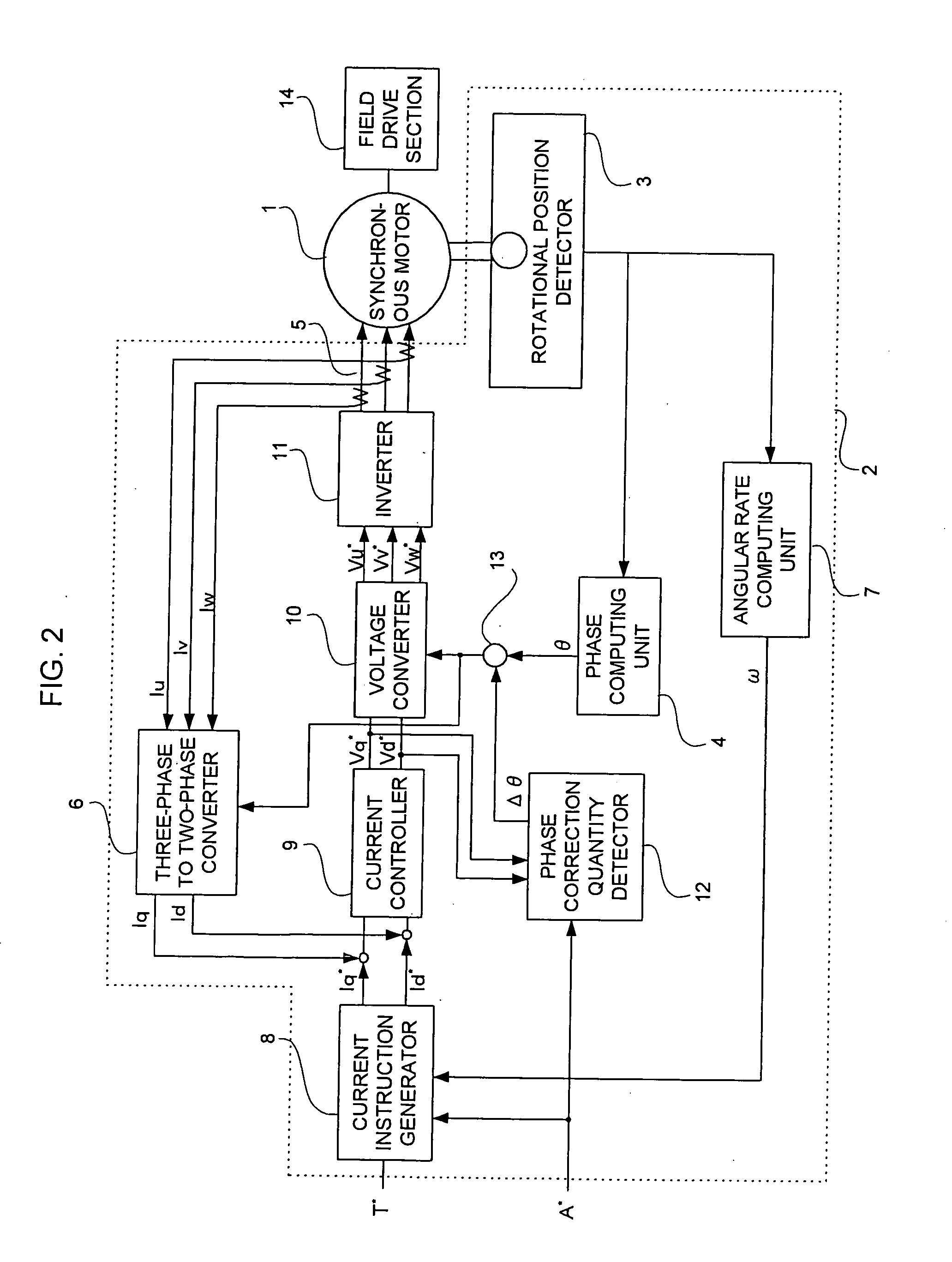
[0040]FIG. 2 is a block diagram showing a synchronous motor control device according to Embodiment 2 of the present invention. In FIG. 2, a phase correction quantity detector is different from that in the synchronous motor control device shown in FIG. 1 and the other parts are the same. The description of the same parts is omitted here.

[0041] The voltage instructions Vd* and Vq* which are the outputs of the current controller 9 are inputted to a phase correction quantity detector 12a.

[0042] The phase correction quantity detector 12a determines the deviation δ by calculating an inverse tangent (arc tangent) of the voltage instructions Vd* and Vq*. The deviation δ is directly outputted as the amount of offset Δθ to the adder 13.

[0043] According to such a synchronous motor control device, the deviation 6 can be directly determined, so that the length of time necessary to correct the deviation is shortened.

embodiment 3

[0044] In the phase correction quantity detector 12 of the synchronous motor control device according to Embodiment 3, a method of determining the amount of offset Δε is different from that in the case of FIG. 1. When Vd* is not zero, an angle of 1° to 180° is scanned as the amount of offset Δθ every 1° to record a value of Vd*. Then, the amount of offset Δθ is determined by interpolation using two amounts of offset in which Vd* is close to zero.

[0045] According to such a synchronous motor control device, the amount of offset is scanned at regular intervals and the amount of offset in which Vd* becomes zero is determined by the interpolation, so that the repetition operation is unnecessary and thus the length of time necessary to determine the amount of offset is shortened.


PUM


Abstract

In a synchronous motor control device that corrects a deviation in rotational position which is related to a rotational position detector for a synchronous motor on which vector-control is performed, the synchronous motor control device includes: a current instruction generator that disables a torque instruction to set d-axis and q-axis current instructions as zero when a phase correction instruction is inputted; a current controller that outputs d-axis and q-axis voltage instructions based on the d-axis and q-axis current instructions; a phase correction quantity detector for determining the amount of offset in which the d-axis voltage instruction becomes zero when the phase correction instruction is inputted and the d-axis voltage instruction is not zero; an adder for adding a rotor positional angle and the amount of offset; and a voltage converter for determining three-phase voltage instructions based on the additional value, the d-axis and q-axis voltage instructions.

Description

BACKGROUND OF THE INVENTION [0001] 1. Field of the Invention [0002] The present invention relates to a synchronous motor control device for correcting a deviation in rotational position of a synchronous motor, and also to a method of correcting the deviation in rotational position of the synchronous motor using the control device. [0003] 2. Description of the Related Art [0004] A conventional method of correcting a deviation caused between a motor rotational position determined from an output of a rotational position detector and an actual motor rotational position includes: a step of detecting a no-load state of a motor by an unloading detector; a step of detecting a motor voltage applied to the windings of a motor by a motor voltage detector; a step of computing d-axis and q-axis voltages from rotational angular information of the rotational position detector and the motor voltage; and a step of correcting a rotational angle such that the d-axis voltage becomes zero (for example, ...

Claims


Application Information

Patent Timeline
Patent Type & Authority Applications(United States)
IPC IPC(8): H02P6/06H02P6/08H02P6/15H02P6/16H02P6/17H02P6/182H02P21/00H02P21/08H02P21/18H02P21/22H02P21/24H02P25/02H02P27/06
CPCH02P25/023H02P21/08H02P25/03
Inventor NISHIMURA, SHINJINAKAYAMA, MASAKAZU
Owner MITSUBISHI ELECTRIC CORP
Why Eureka
Try Eureka