Droplet applying method and droplet applying device, and device and electronic equipment

a technology of droplet and application method, applied in the direction of superimposed coating process, liquid/solution decomposition chemical coating, manufacturing tools, etc., can solve the problems of difficult to obtain irregular film profile, and difficult to achieve wiring with a minute line width. , the effect of reducing or suppressing the occurrence of quality defects

Inactive Publication Date: 2005-05-19
SEIKO EPSON CORP
View PDF4 Cites 3 Cited by
  • Summary
  • Abstract
  • Description
  • Claims
  • Application Information

AI Technical Summary

Benefits of technology

[0025] Thereby, in an exemplary embodiment of the present invention, the discharged droplet has a velocity component in the direction along the substrate surface. As a result, the each droplet landing on the substrate surface does not spread in a dot shape, but spreads linearly elongated by its kinetic momentum, so that a substantially uniform film with less irregularity can be formed. In this case, since the droplet is formed linearly, the occurrence of quality defects, such as disconnection, can be reduced or suppressed. Furthermore, in an exemplary embodiment of the present invention, since the droplet having a constant volume spreads linearly, the width of the line formed of this droplet becomes small, so that a pattern with a minute line width can be formed.

Problems solved by technology

However, such a related art technique as described above has the following problem.
When dot-like droplet is applied two-dimensionally, each dot is independent, and thus in some wet spreading extent of the droplet, a uniform film may not be formed, which makes the film profile irregular.
In this case, there is a possibility of exerting adverse effects on properties of a formed element.
Furthermore, in the case where wiring, such as metal wiring, is formed by droplet discharging, the droplet applied linearly is spread wet and a line width becomes large, thereby making it difficult to obtain wiring with a minute line width.
Furthermore, in the case where forming wiring, when a dot interval is narrowed to secure continuity, a phenomenon that the droplets are aggregated to be large, so that peripheral lines become thin, a so-called bulge occurs, which may cause disconnection.

Method used


Image

  • Droplet applying method and droplet applying device, and device and electronic equipment
  • Droplet applying method and droplet applying device, and device and electronic equipment
  • Droplet applying method and droplet applying device, and device and electronic equipment

Examples


first exemplary embodiment

(First Exemplary Embodiment)

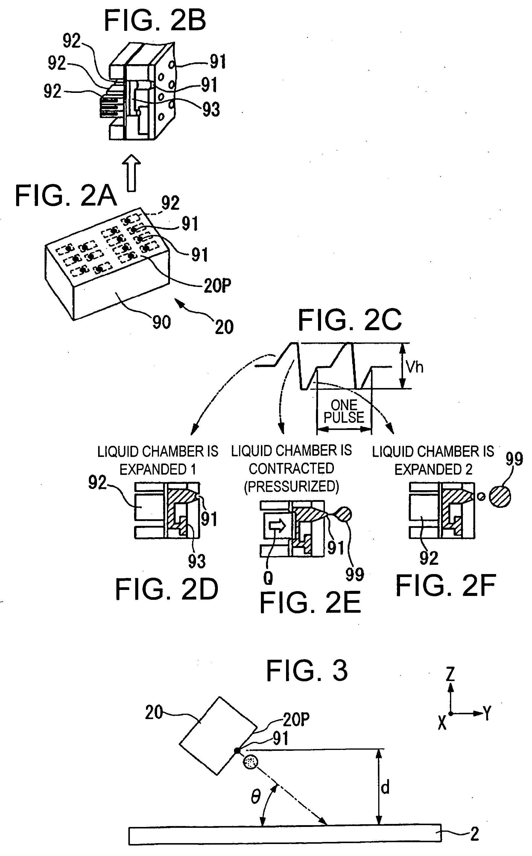
[0038] Firstly, a droplet applying device is described.

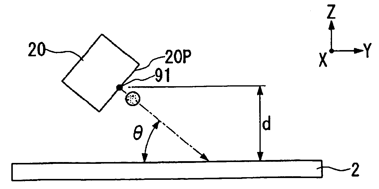
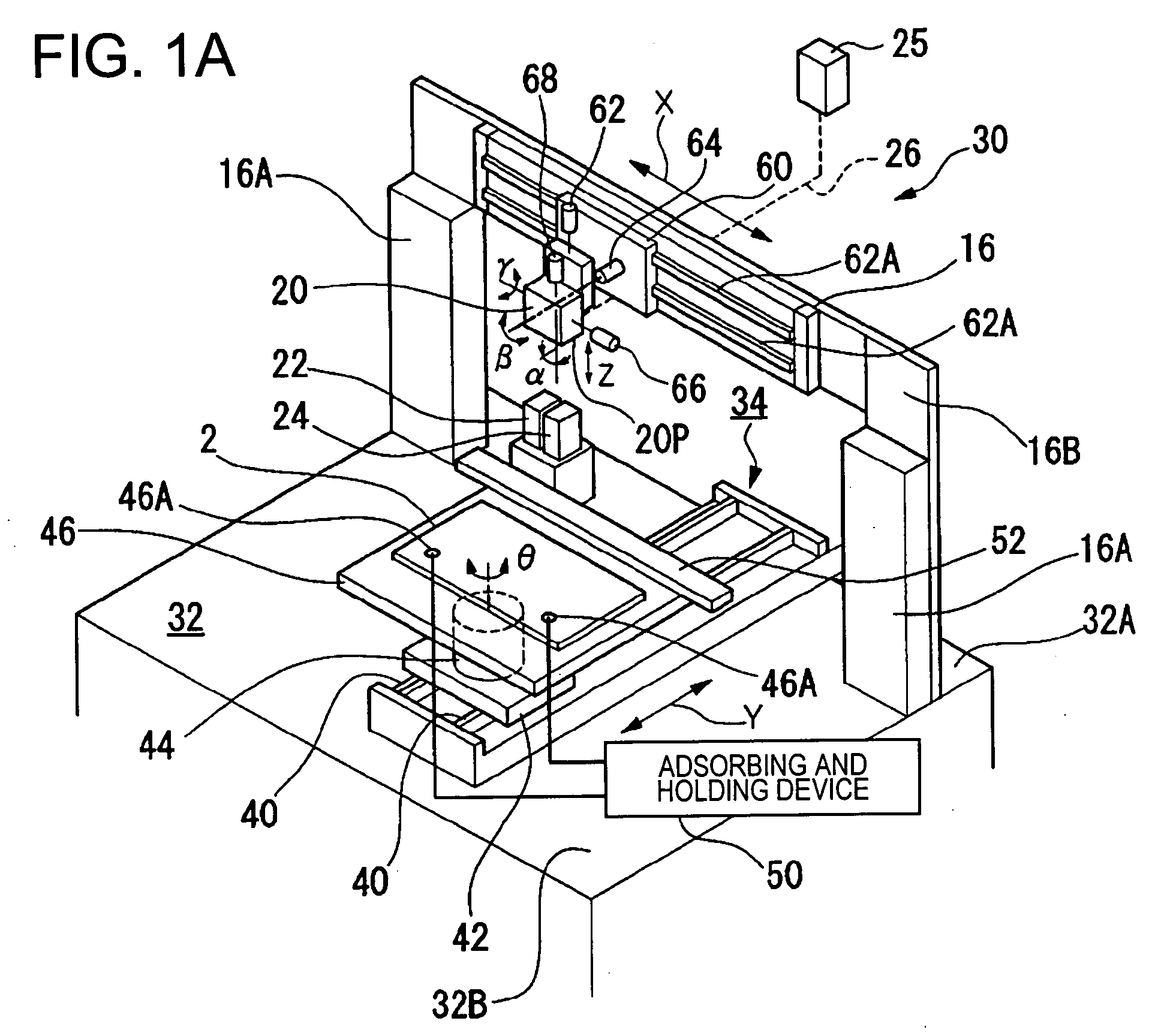
[0039]FIG. 1 is a schematic exterior perspective view of a droplet applying device 30.

[0040] The droplet applying device 30 has a base 32, a first moving device 34, a second moving device 16, electronic balance (a weight measuring device) not shown in the figure, a droplet discharging head 20, a capping unit 22, and a cleaning unit 24 or the like. The first moving device 34, the electronic balance, the capping unit 22, the cleaning unit 24 and the second moving device 16 are set up on the base 32, respectively.

[0041] The first moving device 34 is preferably set up directly on the base 32, and this first moving device 34 is positioned along a Y axial direction. In contrast, the second moving device 16 is mounted upright with respect to the base 32 using supporting columns 16A and 16A, and the second moving device 16 is mounted to a rear part 32A of the base 32. An X axial direction of the second mov...

second exemplary embodiment

(Second Exemplary Embodiment)

[0072] Next, a liquid crystal display device is described as a device manufactured by applying droplets according to the above-mentioned droplet applying method.

[0073] An exemplary embodiment of the present invention can be applied when manufacturing a liquid crystal display device shown in FIGS. 6 through 8. The liquid crystal display device of the present exemplary embodiment is an active matrix type transmissive liquid crystal device using a TFT (Thin Film Transistor) element as a switching element. FIG. 6 is a schematic circuit diagram of switching elements, signal lines or the like in a plurality of pixels arranged in matrix in the transmissive liquid crystal device. FIG. 7 is a partial plan view showing a structure of a plurality of pixel groups adjacent to each other on a TFT array substrate on which data lines, scanning lines, and pixel electrodes or the like are formed. FIG. 8 is a cross-sectional view along plane A-A′ in FIG. 7. In FIG. 8, a c...

third exemplary embodiment

(Third Exemplary Embodiment)

[0083] An exemplary embodiment of the present invention can be used to form a film serving as a component of a color filter.

[0084]FIG. 9 is a schematic showing the color filters formed on a substrate P. As shown in FIG. 9, in this example, a plurality of color filter regions 251 are formed in matrix on the rectangular substrate P in terms of enhancing productivity. These color filter regions 251 can be used as color filters adapted to the liquid crystal display device by cutting the substrate P later.

[0085] The color filter regions 251 are obtained by forming a liquid composition of R (red), a liquid composition of G (green), and a liquid composition of B (blue) in a predetermined pattern, in the present example, in a related art or publicly known conventional striped type pattern.

[0086] As this forming pattern, in addition to the stripe type, a mosaic type, a delta type, a square type, or the like, may be employed. The above-mentioned interfacial acti...


PUM


Abstract

Exemplary embodiments enable formation of a uniform film and a pattern with a minute line width and generate no or substantially no quality defects, such as disconnection. A droplet is discharged from a droplet discharging head to apply in a predetermined region on a surface of a substrate while relatively moving the droplet discharging head and the substrate. The droplet is discharged with respect to the surface of the substrate in a direction intersecting with a vertical direction, and when relatively moving the droplet discharging head and the substrate to discharge the droplet, the droplet is discharged along the relative movement direction.

Description

BACKGROUND OF THE INVENTION [0001] 1. Field of Invention [0002] Exemplary embodiments of the present invention relate to a droplet applying method, a droplet applying device, a device and electronic equipment. [0003] 2. Description of Related Art [0004] Usage of liquid crystal display devices, such as color liquid crystal display devices, has increased with the development of electronic equipment, such as computers and portable information equipment terminals. In this type of liquid crystal display device, a color filter is used to colorize a display image. In some color filters, a substrate is provided and inks (droplets) of R (red), G (green) and B (blue) are landed on this substrate in a predetermined pattern, and these inks are dried on the substrate, thereby forming a coloring layer. As a method for landing the inks on, and applying to, the substrate, for example, a drawing machine by an ink-jet method (droplet discharging method) is employed. [0005] In the case where the ink-j...

Claims


Application Information

Patent Timeline
Patent Type & Authority Applications(United States)
IPC IPC(8): B05C5/00B41J2/01B05D1/02B05D1/26B05D7/00H01L51/00H05K3/12
CPCH05K3/1241H01L51/0004H10K71/13B05D1/02
Inventor MIURA, HIROTSUNA
Owner SEIKO EPSON CORP
Why Eureka
Try Eureka