Eureka AIR delivers breakthrough ideas for toughest innovation challenges, trusted by R&D personnel around the world.

Magnetic storage unit using ferromagnetic tunnel junction element

Inactive Publication Date: 2005-05-19
SONY CORP
View PDF4 Cites 0 Cited by
  • Summary
  • Abstract
  • Description
  • Claims
  • Application Information

AI Technical Summary

Benefits of technology

[0018] By alternating the current flowing through the word lines, the potential difference, which generates between the word line and the peripheral semiconductor substrate, is reversed with time, thereby preventing electromigration due to an always constant potential difference from occurring, improving resistance to electromigration without increasing the width of the word lines that increases the size of the magnetic storage apparatus, and extending the lifetime by preventing troubles of the magnetic storage apparatus.
[0019] Particularly, in the case of inverting the direction of the current flowing through the word lines at every time of writing in the ferromagnetic tunnel junction devices, it is possible to minimize the time to generate a constant potential difference between the word line and the peripheral semiconductor substrate, thereby more effectively preventing electromigration from occurring and further improving resistance to electromigration.

Problems solved by technology

Consequently, electromigration is occurs due to the current flowing through the word line in the fixed direction and the potential difference generated between the word line and peripheral area thereof and separates out a metal or metals consisting of the word line, thereby causing a short-circuit between the word lines, damage of the word lines themselves, etc.
Accordingly, there is a fear of incurring troubles in the magnetic storage apparatus.
A possible solution to prevent such electromigration from occurring is to improve the resistance to electromigration of the word lines by increasing the width of the word lines; however, this is accompanied by another problem of increasing the size of the magnetic storage apparatus due to the increased width of the word lines.

Method used


Image

  • Magnetic storage unit using ferromagnetic tunnel junction element
  • Magnetic storage unit using ferromagnetic tunnel junction element
  • Magnetic storage unit using ferromagnetic tunnel junction element

Examples


Embodiment Construction

[0030] In what follows, a concrete embodiment of the present invention will be described by reference to the drawings.

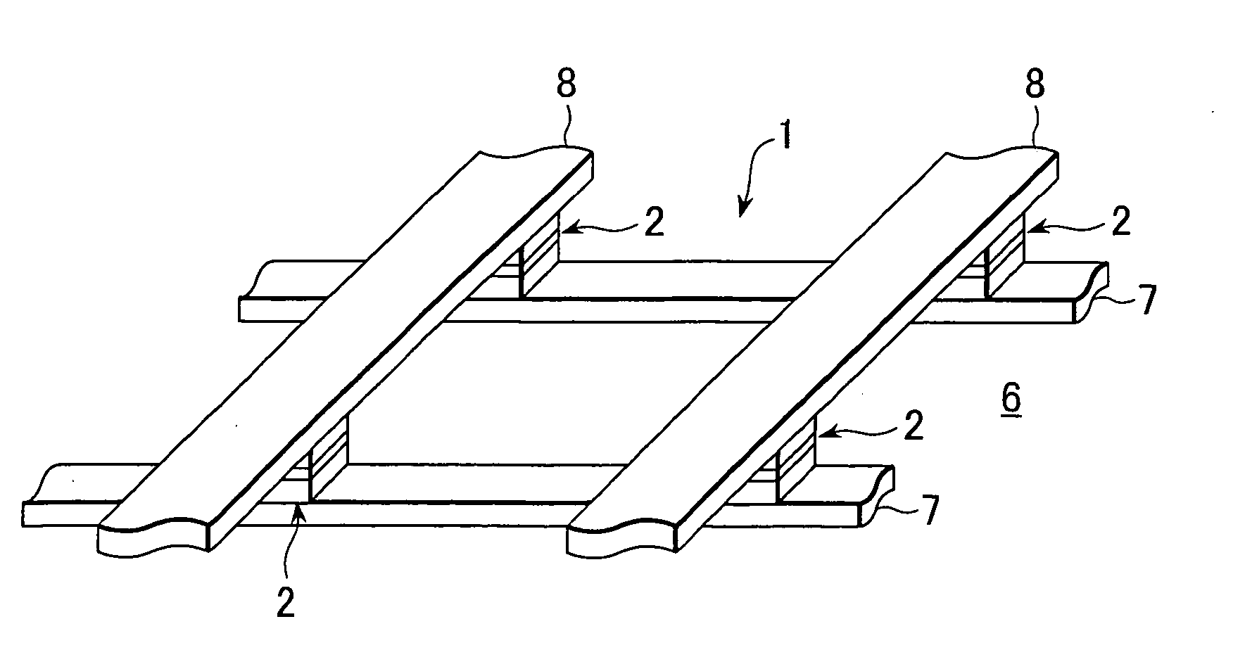
[0031] The magnetic storage apparatus 1 according to the present invention uses ferromagnetic tunnel junction devices 2 as storage elements each of which stores two different memory states, for example, either “0” or “1”.

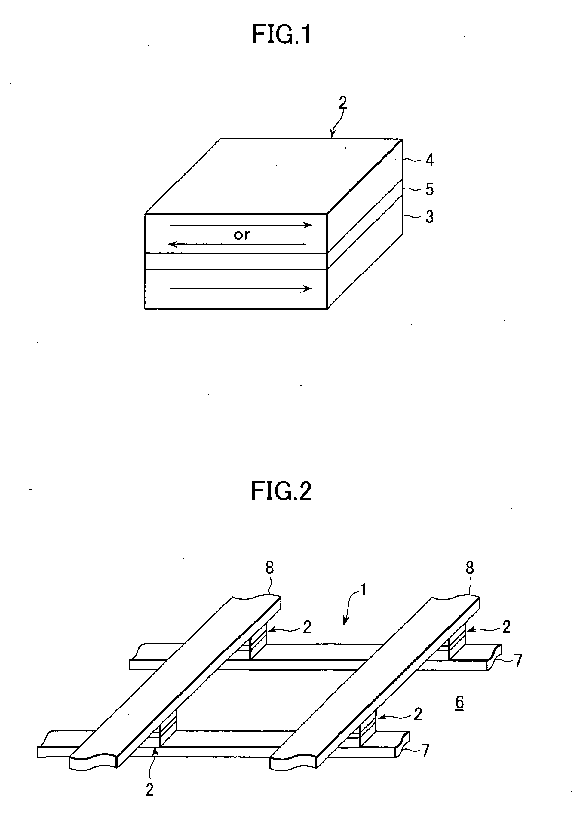
[0032] Firstly, describing the structure of the ferromagnetic tunnel junction device 2, as shown in FIG. 1, the ferromagnetic tunnel junction device 2 is made of a lamination in which a thin film fixed magnetization layer 3 and a thin film free magnetization layer 4 are laminated on top and back surfaces of a tunnel barrier layer 5.

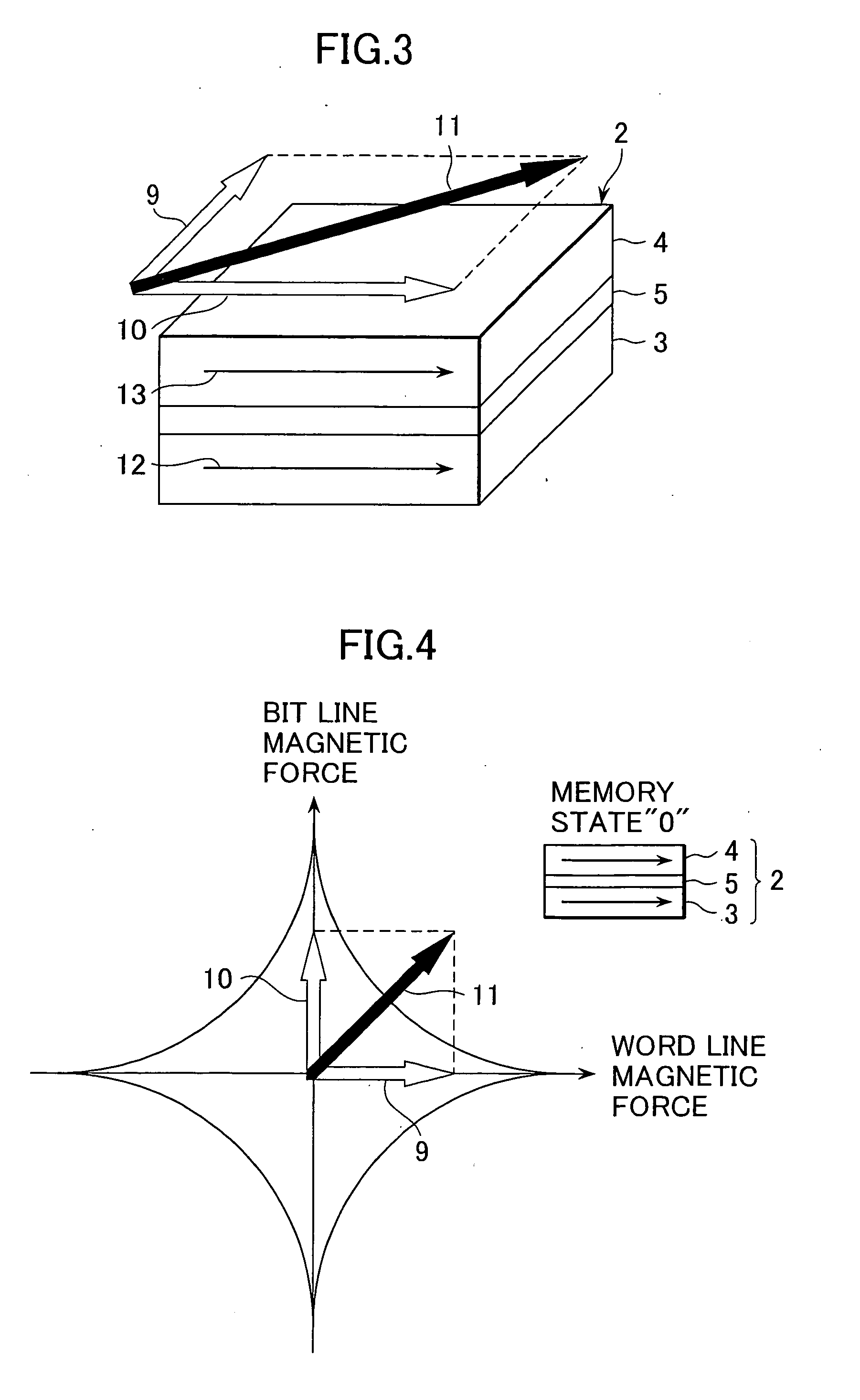
[0033] It is to be noted here that the fixed magnetization layer 3 is made of a ferromagnetic material (for example, CoFe) and is magnetized always in a fixed direction. On the other hand, the free magnetization layer 4 is made of a ferromagnetic material (for example, NiFe) and magnetized in the same direction (paralle...


PUM


Abstract

A magnetic storage apparatus provided using ferromagnetic tunnel junction devices is constituted by forming the ferromagnetic tunnel junction device by laminating a fixed magnetization layer and a free magnetization layer on top and back surfaces of a tunnel barrier layer, respectively, wiring word lines in the magnetization direction of the fixed magnetization layer of the ferromagnetic tunnel junction device, and wiring bit lines in the direction orthogonal to the magnetization direction of the fixed magnetization layer of the ferromagnetic tunnel junction device, wherein two different memory states can be written in the ferromagnetic tunnel junction device by inverting the direction of the current flowing through the bit lines. At the time of writing in the ferromagnetic tunnel junction device, the direction of the current flowing through the word line is inverted in the same direction as or the opposite direction to the magnetization direction of the fixed magnetization layer.

Description

FIELD OF TECHNOLOGY [0001] The present invention relates to a magnetic storage apparatus using ferromagnetic tunnel junction devices. BACKGROUND TECHNOLOGY [0002] In recent years, as a storage apparatus for a computer, it is desirable to have one capable of writing at a high speed and an unlimited number of times and that is a nonvolatile type. [0003] A magnetic storage apparatus using ferromagnetic tunnel junction devices is attracting attention as a storage apparatus that is provided with the above mentioned functions. [0004] Such a ferromagnetic tunnel junction device is constituted by laminating a pair of ferromagnetic thin films on both the top and back surfaces of an insulation thin film. One of the ferromagnetic thin films is called a fixed magnetization layer because it is always magnetized in a fixed direction. Here, on the other hand, the other ferromagnetic thin film is called a free magnetization layer because it is magnetized in the same direction (parallel direction) a...

Claims


Application Information

Patent Timeline
IPC IPC(8): G11C11/14G11C11/15H01L21/8246H01L27/105H01L43/08
CPCG11C11/16G11C11/14G11C11/15H01L27/105
Inventor MORIYAMA, KATSUTOSHIMORI, HIRONOEUOKAZAKI, NOBUMICHI
Owner SONY CORP
Why Eureka
Eureka Blog
Learn More