Al technical title is built by PatSnap Al team. It summarizes the technical point description of the patent document.
a technology of light pulse and stretcher, which is applied in the direction of instruments, photomechanical equipment, active medium materials, etc., can solve the problem of becoming even more susceptible to being out of specification
Active Publication Date: 2005-05-19
CYMER INC
View PDF57 Cites 25 Cited by
Summary
Abstract
Description
Claims
Application Information
AI Technical Summary
This helps you quickly interpret patents by identifying the three key elements:
Problems solved by technology
Method used
Benefits of technology
Problems solved by technology
Some lasers manufactured by applicants' assignee, e.g., XLA lasers, are borderline passing tests for spatial coherence according to current practice and may become even more susceptible to being out of specification in the future as specifications are defined more tightly.
However this data point does not represent the property of coherence of the whole beam.
Method used
Image
Click on the blue label to locate the original text in one second.
Reading with bidirectional positioning of images and text.
Examples
Embodiment Construction
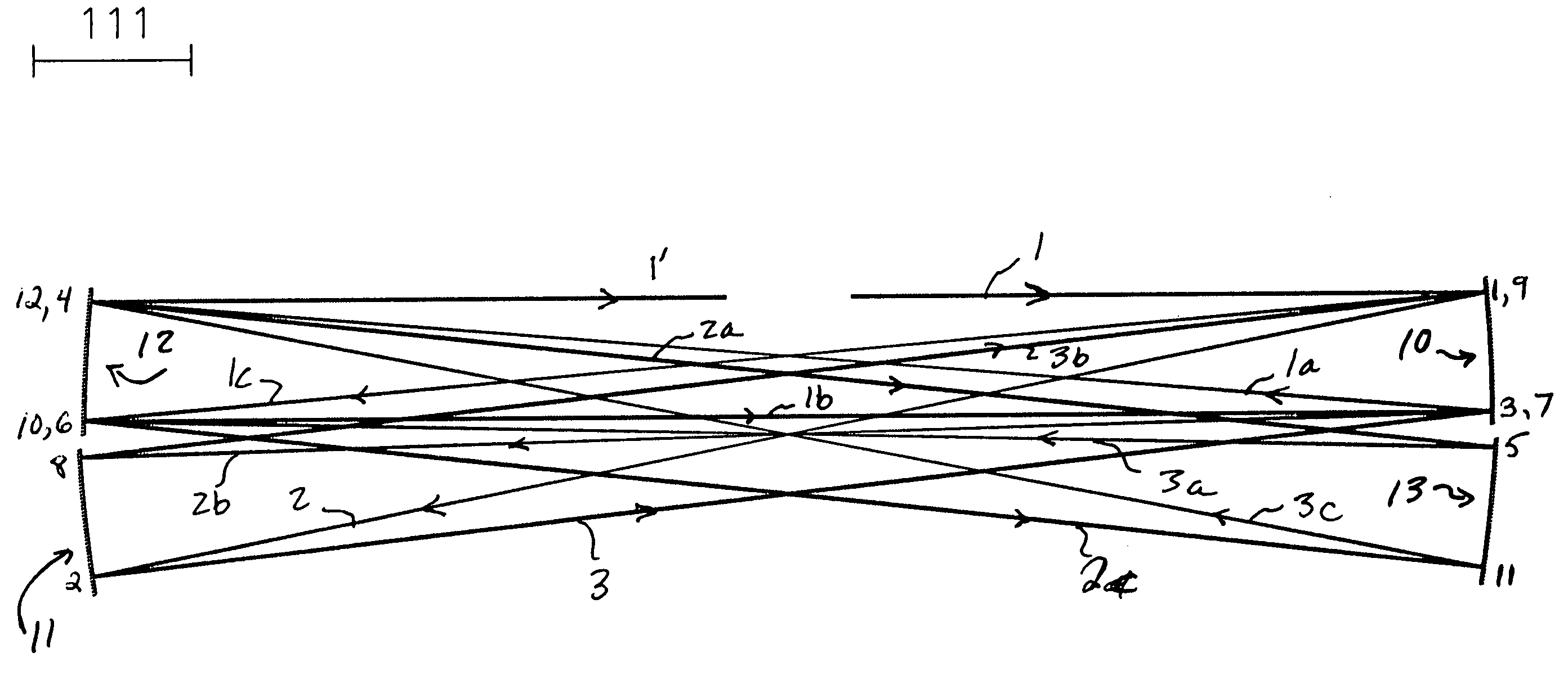
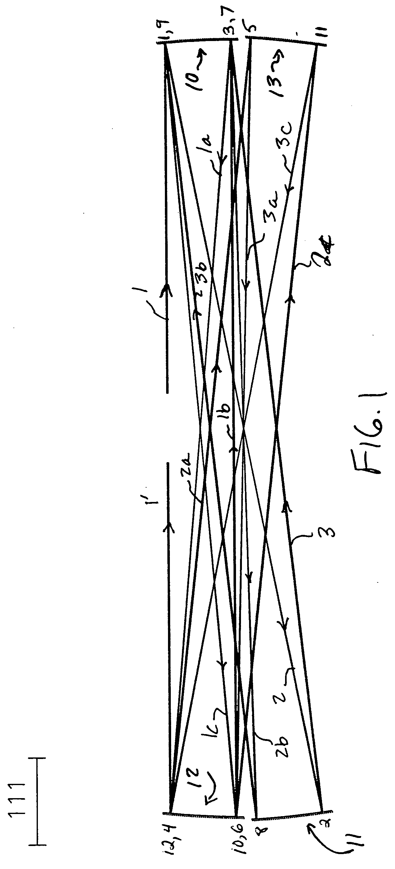
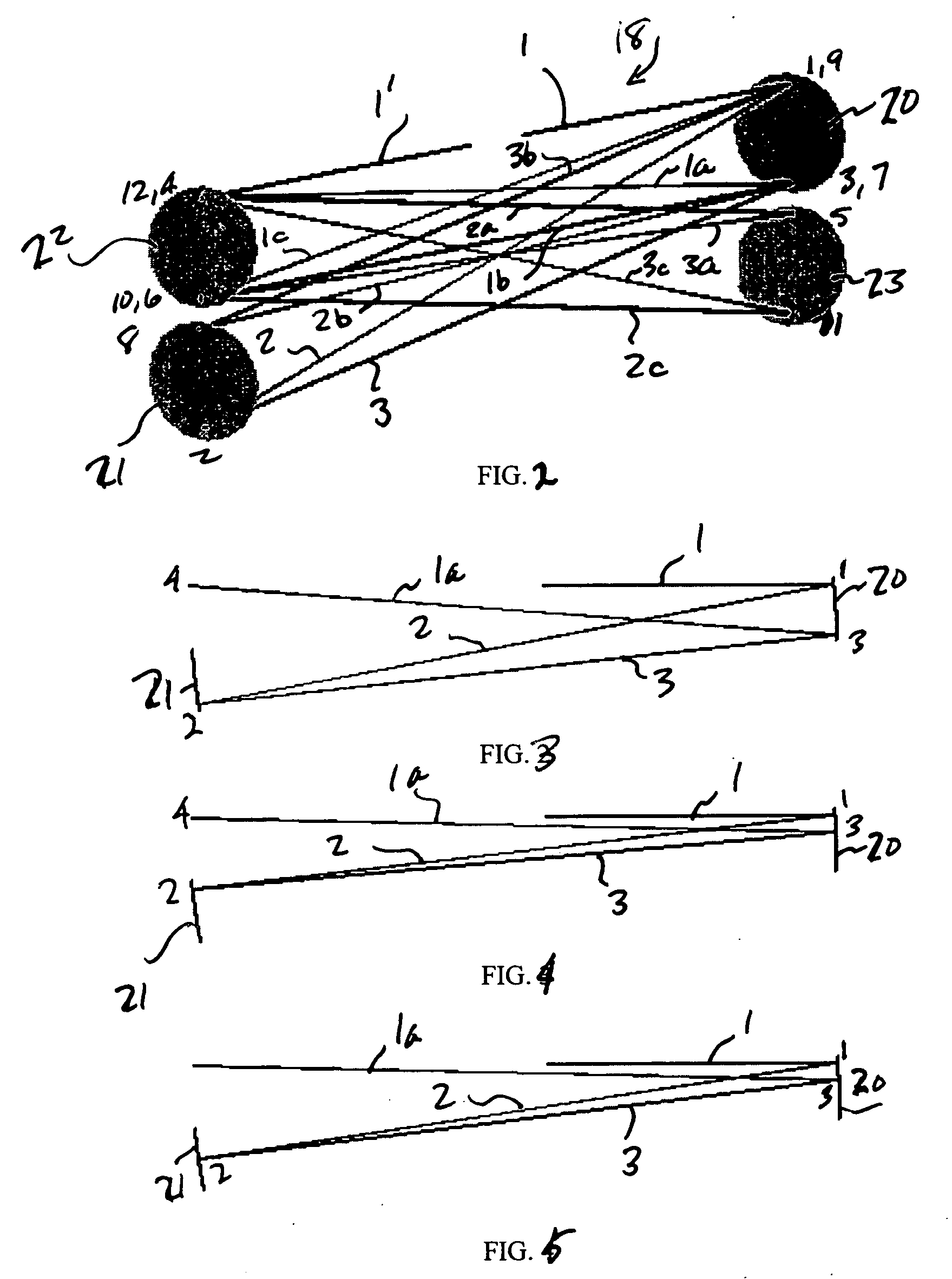
[0013] According to aspects of an embodiment of the present invention applicant has designed an optical pulse stretcher for a laser light source, e.g., a gas discharge laser light source, e.g., a KrF or ArF or molecular fluorine gas discharge laser, e.g., for use in integrated circuitry lithography illumination, which has a long optical delay, but is constrained to have a practical physical length, e.g., less than about 8 feet, e.g., in order to be mounted on existing laser frames or contained within a beam delivery unit and fit, e.g., in a fabrication facility clean room sub-floor room. According to aspects of an embodiment of the present invention, the pulse stretcher may be, e.g., a multi-passing system with a minimum number of optics, e.g., four, consistent with proper operation. This, in addition, e.g., minimizes the number of adjustments necessary to align a system, and according to aspects of an embodiment of the present invention the system is designed to allow for a conside...
PUM
Abstract
An apparatus and method for providing a high peak power short pulse duration gas discharge laser output pulse is disclosed which may comprise a pulse stretcher which may comprise a laser output pulse optical delay initiating optic diverting a portion of the output laser pulse into an optical delay having an optical delay path and comprising; a plurality of confocal resonators in series aligned to deliver an output of the optical delay to the laser output pulse optical delay initiating optic. The plurality of confocal resonators comprises four confocal resonators comprising a twelve pass four mirror arrangement. Each of the plurality of confocal resonators may comprise a first concave spherical mirror having a radius of curvature and a second concave spherical mirror having the same radius of curvature and separated by the radius of curvature. The pulse stretcher may comprise a first confocal resonator cell which may comprise: a first concave spherical mirror having a radius of curvature receiving an input beam from the laser output pulse optical delay initiating optic comprising the portion of the output laser pulse at a first point on a face of the first concave spherical mirror and generating a first reflected beam; a second concave spherical mirror having the same radius of curvature and separated from the first concave spherical mirror by the radius of curvature and receiving the first reflected beam at a first point on a face of the second concave spherical mirror and generating a second reflected beam incident on a second point on the face of the first concave spherical mirror, the second reflected beam being reflected by the first concave spherical mirror from the second point on the first mirror to form an output beam from the first confocal resonator cell; and, a second confocal resonator cell receiving the output beam of the first confocal resonator cell as an input beam of the second confocal resonator cell. The apparatus and method may form part of a beam delivery unit and may be part of an integrated circuit lithography lights source or an integrated circuit lithography tool. The apparatus and method may comprise a plurality, e.g., two pulse stretchers in series and may include spatial coherency metrology.
Description
RELATED APPLICATIONS [0001] The present application is a continuation-in-part of U.S. patent application Ser. No. 10 / 712,545 filed on Nov. 13, 2003, entitled LONG DELAY AND HIGH TiS PULSE STRETCHER and related to U.S. Published Patent Application No. 2002 / 0154671A1, published on Oct. 24, 2002 with inventors Knowles et al., entitled LINE SELECTED F2 TWO CHAMBER LASER SYSTEM, based upon an application Ser. No. 10 / 056,619, filed on Jan. 23, 2002 (Attorney Docket No. 1999-0013-01, and of U.S. Published Patent Application No. 2003 / 0138019A1, published on Jul. 24, 2003, with inventors Rylov et al., entitled TWO CHAMBER F2 LASER SYSTEM WITH F2 PRESSURE BASED LINE SELECTION, based on an application Ser. No. 10 / 243,102, filed on Sep. 13, 2002 Attorney Docket No. 2002-0074-01, and to U.S. Pat. Nos. 6,067,311, entitled EXCIMER LASER WITH PULSE MULTIPLIER, issued to Morton et al. on May 23, 2000, based upon an application Ser. Nos. 09 / 148,514, filed on Sep. 4, 1998, and 6,314,119, entitled EXCI...
Claims
Application Information
Patent Timeline
Application Date:The date an application was filed.
Publication Date:The date a patent or application was officially published.
First Publication Date:The earliest publication date of a patent with the same application number.
Issue Date:Publication date of the patent grant document.
PCT Entry Date:The Entry date of PCT National Phase.
Estimated Expiry Date:The statutory expiry date of a patent right according to the Patent Law, and it is the longest term of protection that the patent right can achieve without the termination of the patent right due to other reasons(Term extension factor has been taken into account ).
Invalid Date:Actual expiry date is based on effective date or publication date of legal transaction data of invalid patent.
Patent Type & Authority Applications(United States)