Miniature fan or micro-fan

a fan or micro-fan technology, applied in the direction of mechanical equipment, electrical equipment, dynamo-electric machines, etc., can solve the problems of large motor in relation to the overall, disadvantageous in terms of flow rate (v/t), pressure increase p of the fan, etc., and achieve the effect of increasing the number of functions

Inactive Publication Date: 2005-05-19
EBM PAPST ST GEORGEN & -
View PDF11 Cites 66 Cited by
  • Summary
  • Abstract
  • Description
  • Claims
  • Application Information

AI Technical Summary

Benefits of technology

[0012] According to the invention, this object is achieved by arranging a rotor position sensor centrally but other control components outside the air duct. It is thereby possible to mount the at least one rotor position sensor in space-saving fashion on the motor region of the circuit board configuration, and to arrange other components in a component region outside the air duct, thus allowing the annular air flow cross section to be made larger than previously. This permits larger fan blades to be used, and thus a greater flow rate and / or a greater pressure increase to be achieved for the same physical size.
[0014] These approaches to achieving the object of the present invention create the possibility of increasing the number of functions for a miniature fan or micro-fan. For example, when miniature fans or micro-fans are used in open- or closed-loop control systems or management systems, they must not generate any electromagnetic interference, i.e. their electromagnetic compatibility (EMC) must meet high standards; this requires more components and more-complex circuits, which the invention now makes possible for the first time in compact form for miniature fans and micro-fans as well.

Problems solved by technology

In fans that are driven by an electronically commutated external-rotor motor, the motor is large in relation to the overall size of the fan, which is disadvantageous in terms of the flow rate (V / t) and pressure increase Δp of the fan.

Method used


Image

  • Miniature fan or micro-fan
  • Miniature fan or micro-fan
  • Miniature fan or micro-fan

Examples


Embodiment Construction

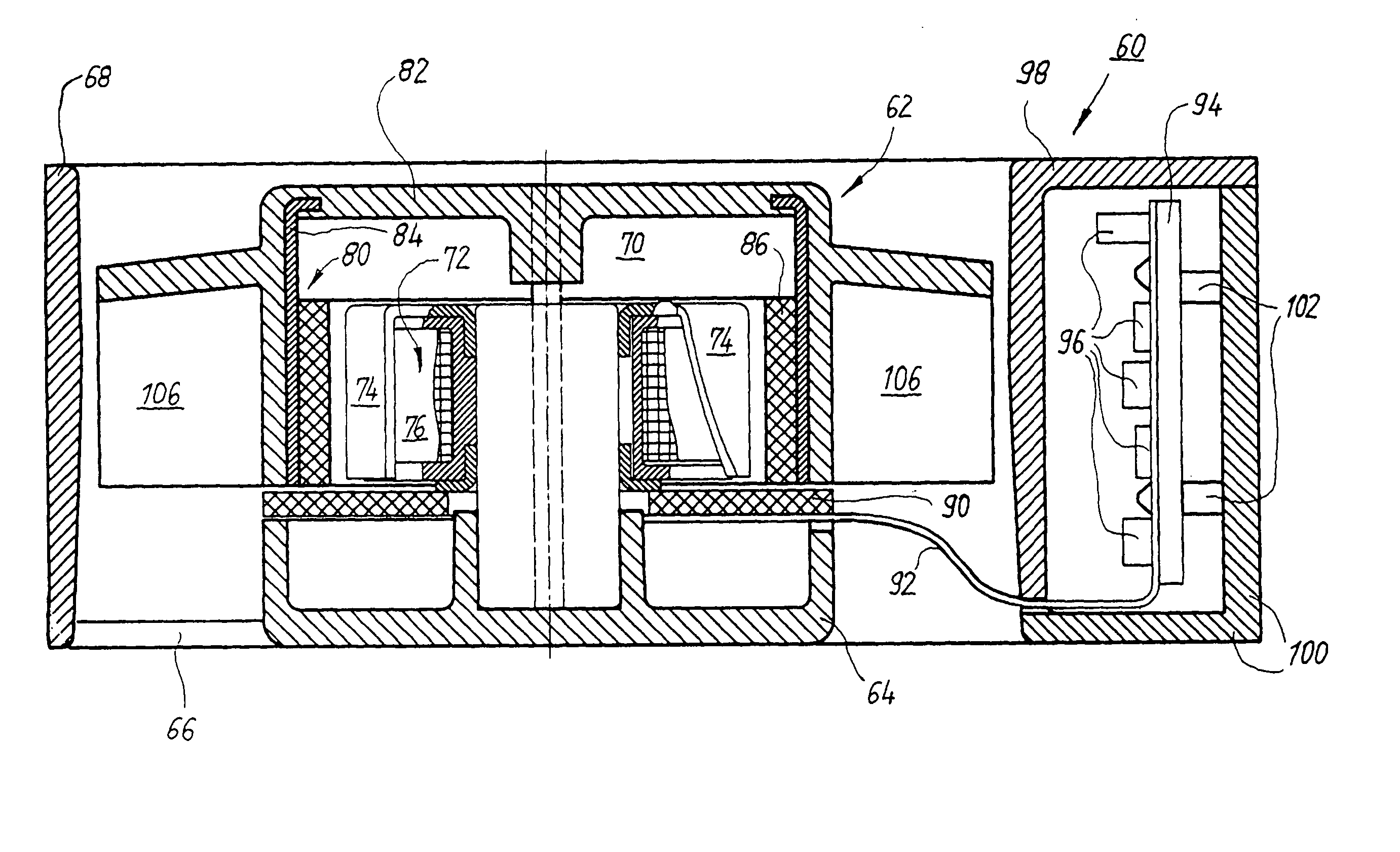
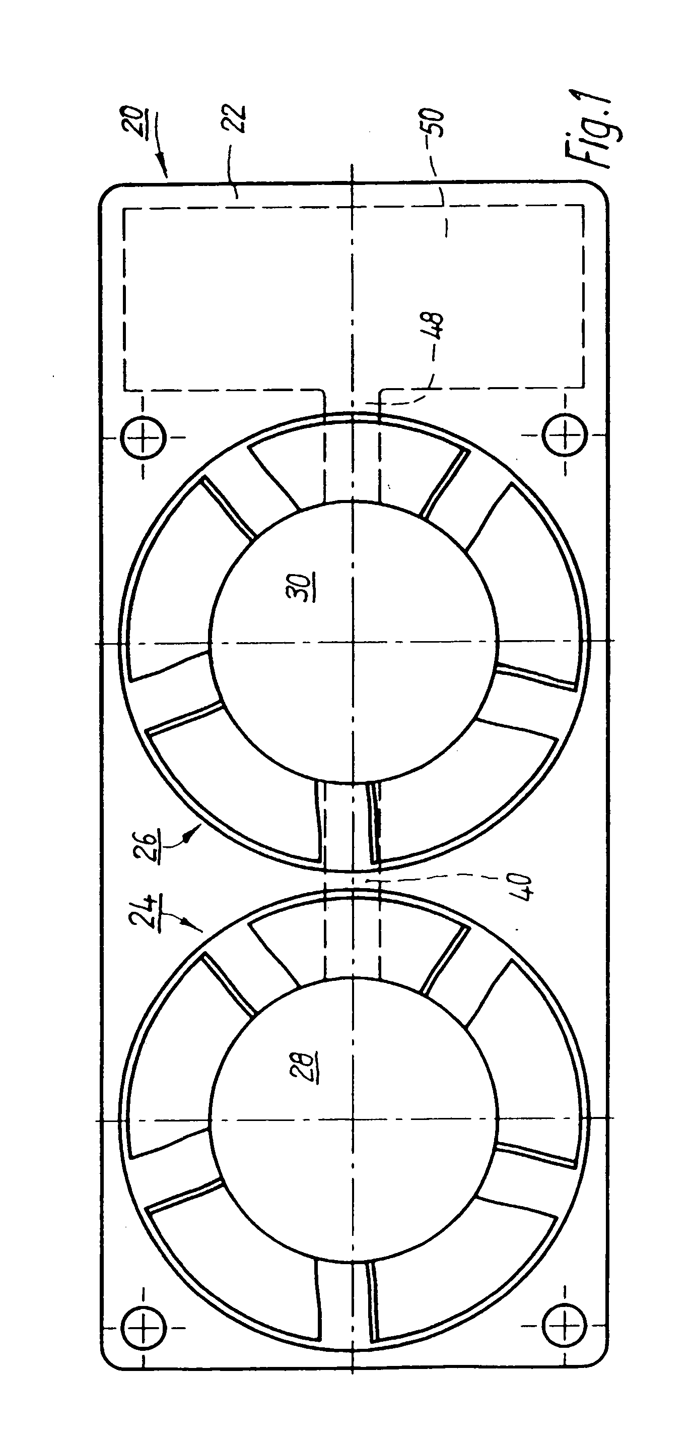
[0024]FIG. 1 shows, at greatly enlarged scale, a double fan 20 comprising a housing 22 in which two miniature fans or micro-fans 24, 26, each driven by an electronically commutated external-rotor motor 28, 30, are arranged next to one another. These motors 28, 30 are rigidly connected to housing 22 by way of struts (not depicted).

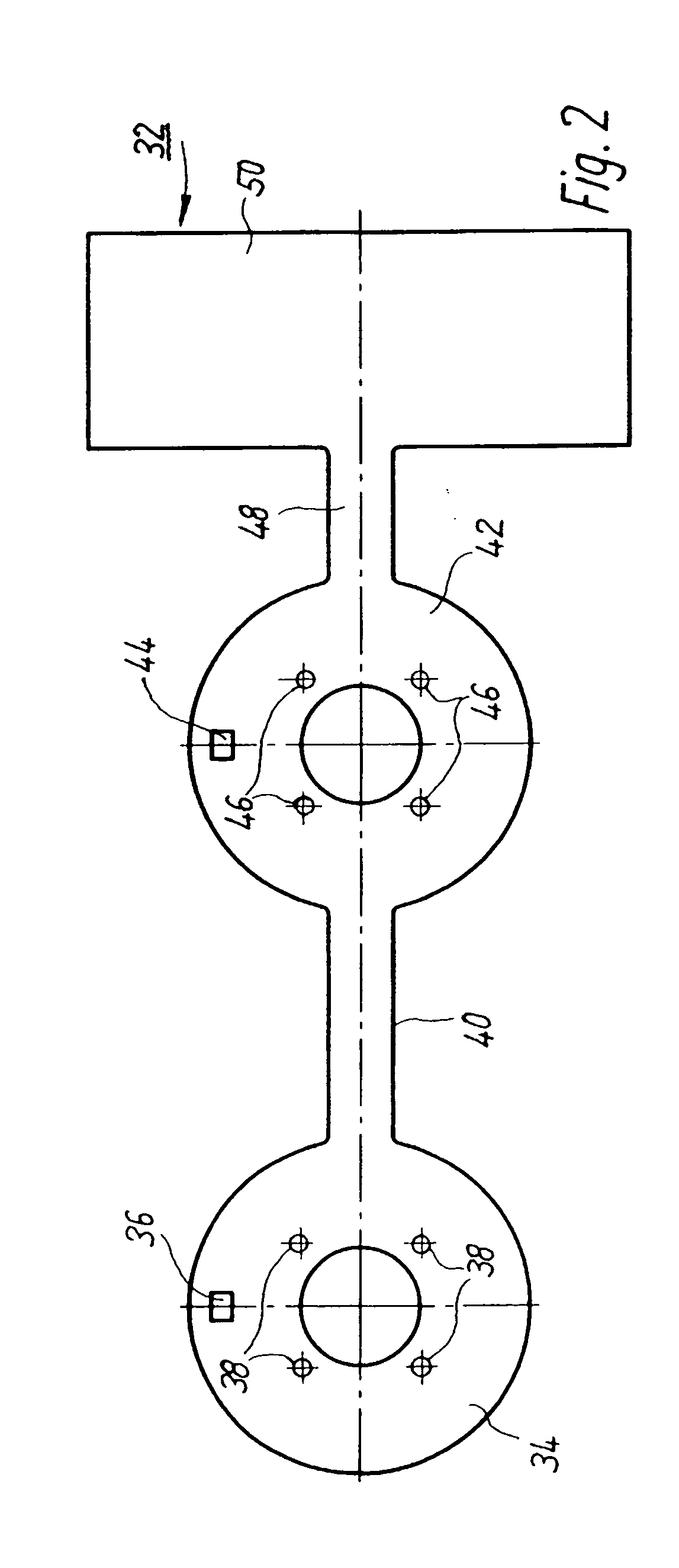
[0025] According to the invention and as shown in FIG. 2, a circuit board 32 that has, for motor 28, a first approximately annular part 34, on which a Hall IC 36 and four attachment points 38 for the winding ends of motor 28 are provided, is used in the double fan of FIG. 1. Part 34 is connected, via a first bridge 40 comprising printed conductors (not depicted), to a second approximately annular part 42 on which are located a Hall IC 44 and four attachment points 46 for the winding ends (not depicted) of motor 30.

[0026] Part 42 is connected, via a second bridge 48 comprising printed conductors (not depicted), to an (in this case, rectangular) part 50 on ...


PUM


Abstract

A miniature fan or micro-fan (200) features a fan housing (150) through which a substantially annular air duct extends in the axial direction, there being arranged in a central region of the air duct an electronically commutated external-rotor motor (202) whose external rotor, equipped with at least one permanent magnet (86), carries an impeller wheel (204) that is arranged rotatably in the air duct. A circuit board configuration (168) has a motor region that is arranged in the central region of the air duct and carries at least one galvanomagnetic rotor position sensor that is controllable by the magnetic field of the permanent magnet (86) provided on the external rotor. The board has a component region for the reception of electronic components (170) of the external-rotor motor, which component region is arranged substantially outside the air duct, and which comprises a bridge portion, via which the motor region of the circuit board configuration is electrically connected to the component region (168).

Description

[0001] This application is a section 371 of PCT / EP02 / 13822, filed 6 DEC. 2002 and published 17 Jul. 2003 as WO 03-058 796-A1.FIELD OF THE INVENTION [0002] The invention relates to a miniature fan or micro-fan that is driven by an electronically commutated external-rotor motor. BACKGROUND [0003] Miniature fans or micro-fans serve, for example, to cool processors in computer, to cool small devices, etc., and they have very small dimensions. For example: [0004] fans of PAPST series 250 have dimensions of 8×25×25 mm, [0005] those of PAPST series 400F, dimensions of 10×40×40 mm, [0006] those of PAPST series 400, 20×40×40 mm, [0007] those of PAPST series 500, 50×50×15 mm, and [0008] those of PAPST series 600, 60×60×25 mm. [0009] The power consumption of such fans is 0.4-0.6 W for series 250, 0.7-0.9 W for series 400F, 0.9-1.6 W for series 400, and 0.8-3.4 W for series 600. This defines the preferred field of application of the present invention. [0010] In fans that are driven by an electr...

Claims


Application Information

Patent Timeline
Patent Type & Authority Applications(United States)
IPC IPC(8): F04D25/06H02K7/14H02K11/215H02K11/33H02K29/08
CPCH02K7/14H02K11/0021F04D25/0646H02K29/08F04D25/0633H02K11/0073H02K11/215H02K11/33
Inventor WINKLER, WOLFGANG ARNO
Owner EBM PAPST ST GEORGEN & -
Why Eureka
Try Eureka