
Interposer with electrical contact button and method

a technology of interposer and button, which is applied in the direction of electrical apparatus construction details, fixed connections, electric connection formation of printed elements, etc., can solve the problems of not allowing field replacibility of chip modules, unreliable ball grid arrays on large areas, and each suffering from serious problems

Active Publication Date: 2005-05-19
GLOBALFOUNDRIES US INC
View PDF36 Cites 94 Cited by
  • Summary
  • Abstract
  • Description
  • Claims
  • Application Information

AI Technical Summary

Benefits of technology

The present invention relates to an interposer that connects a module to a printed wiring board. The interposer has a hollow body with electrically conductive material and a via that is in registration with connectors on the module and printed wiring board. The hollow body can have voids, and the electrically conductive material can be selected from a variety of metals. The interposer can be fabricated by forming a sacrificial post, patterning electrically conductive material on the sacrificial post, and removing the sacrificial post. The invention also includes a method for fabricating an electrical contact button by forming a pattern of electrically conductive material on a sacrificial post and removing the sacrificial post. The interposer and method provide improved electrical connection between the module and printed wiring board.

Problems solved by technology

Ball grid arrays are unreliable on large areas because the lateral thermal coefficient of expansion driven stresses that develop exceed the ball grid array strength.
Column grid arrays hold together despite the stresses but are soldered solutions and, thus, do not allow field replacibility of the chip modules.
Each suffers from serious problems.
A disadvantage is that the composite of elastomer and silver particles is itself a poor elastomer.
In other words it undergoes significant plastic deformation under typical operating conditions and leads to eventual failure.
However, they have a disadvantage of being expensive because of the button-by-button fabrication method.
Such high forces, once multiplied by the large number of buttons on an interposer, can cause deformation of the MCM and the PWB, and have been known to crack the chips mounted on the MCM.
Further, these interposers do not scale reliably to larger MCMs with higher input / output (I / O) requirements.
In addition, these interposers are also inconsistent with the introduction of organic packaging.
Organic packages are much softer and more fragile and could thus only tolerate LGA forces much smaller than 100 to 200 grams per button.

Method used


Image

  • Interposer with electrical contact button and method
  • Interposer with electrical contact button and method
  • Interposer with electrical contact button and method

Examples


Embodiment Construction

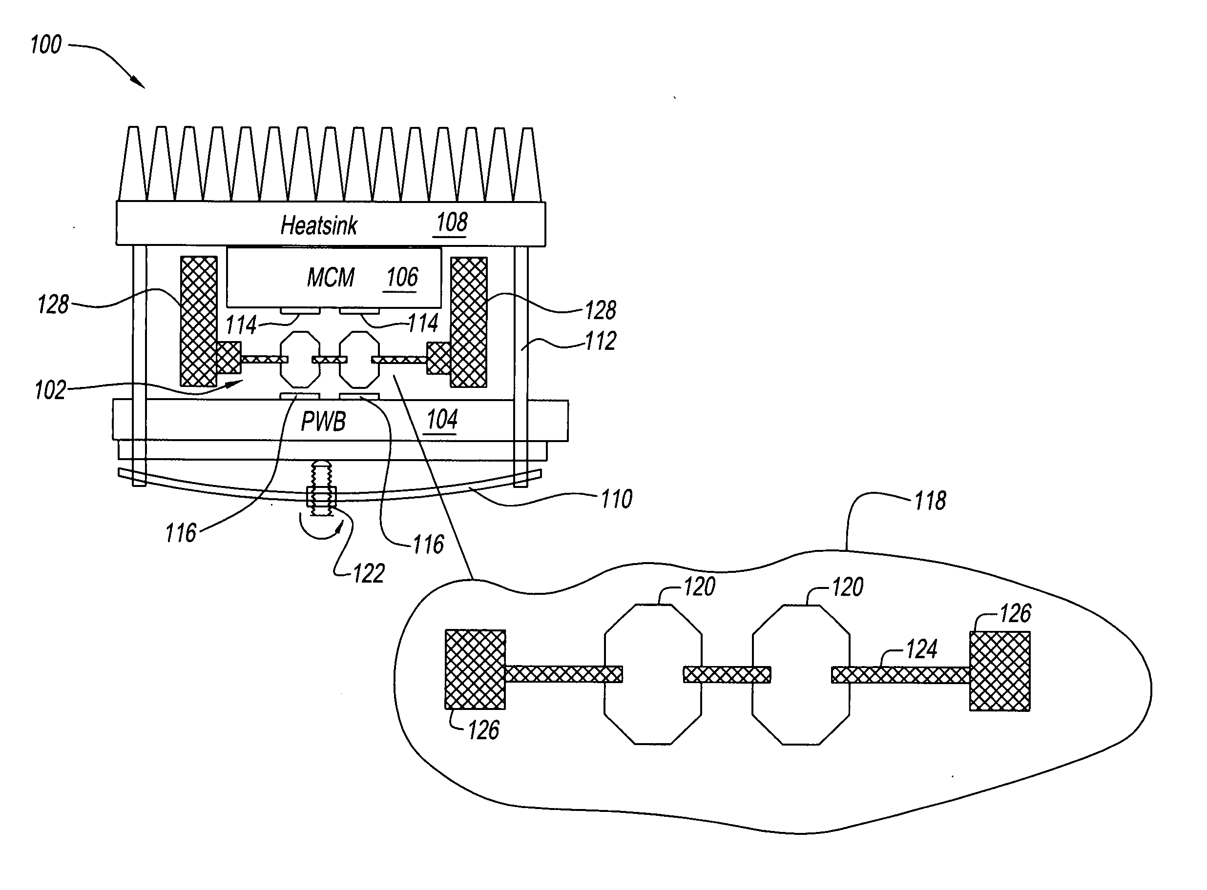
[0052] Referring to FIG. 1, an assembly 100 includes an LGA interposer 102 disposed between a PWB 104 and an MCM module 106, a heat sink 108, a spring 110 and posts 112. PWB 104, MCM module 106 and heat sink 108 are held together under force supplied by spring 110, transferred through posts 112, posts 112 being attached to heat sink 108. Posts 112 are preferably metallic.

[0053] MCM module 106 includes one or more electrical contacts 114 and PWB 104 includes one or more electrical contacts 116 disposed in aligned and spaced relationship to contacts 114. LGA interposer 102, which is shown in an exploded view at detail 118, includes one or more electrical contact buttons 120 disposed in aligned relationship to contacts 114 and 116.

[0054] When spring 110 is adjusted by means of adjuster 122, PWB 104, LGA interposer 102 and MCM module 106 are pressed toward one another so that contacts 114 of MCM module 106 and contacts 116 of PWB 104 make a forced physical and electrical contact with ...


PUM

PropertyMeasurementUnit
electrically conductiveaaaaaaaaaa
electrically insulatingaaaaaaaaaa
metallicaaaaaaaaaa

Abstract

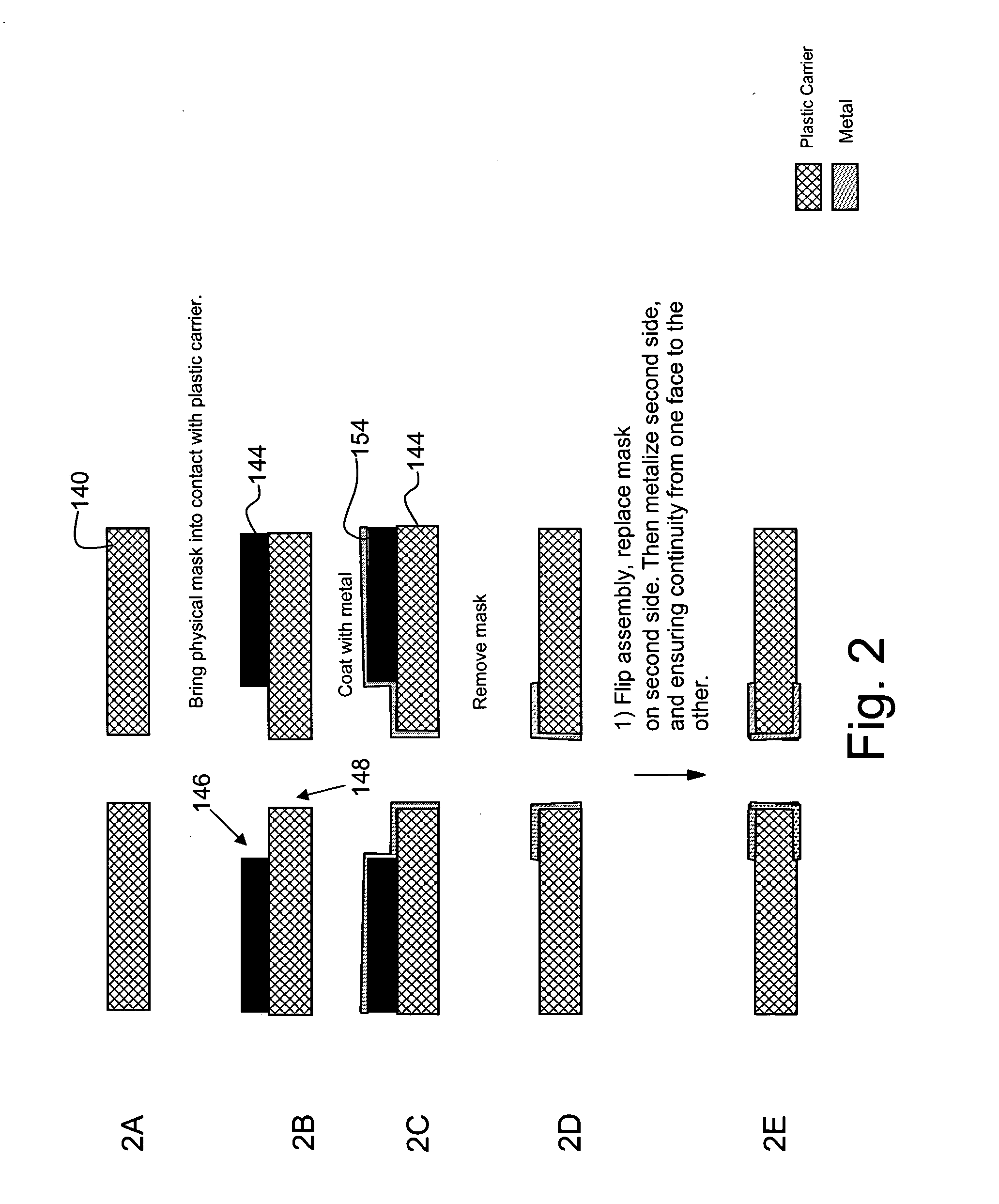
An interposer having one or more hollow electrical contact buttons disposed in a carrier. The interposer is formed by disposing sacrificial posts in vias of the carrier. The electrical contact buttons are formed on the sacrificial posts by a metallizing process in desired pattern using a mask. The sacrificial posts are made of a material that thermally decomposes upon application of heat without altering the carrier or the electrical contact buttons.

Description

FIELD OF THE INVENTION [0001] This invention relates to an interposer with electrical contact buttons and a method for making the electrical contact buttons and the interposer. BACKGROUND OF THE INVENTION [0002] Land Grid Array (LGA) interposers provide an array of interconnections between a printed wiring board (PWB) and a chip module, such as a Multi-Chip Module (MCM). LGA interposers allow connections to be made in a way that are reversible and that do not require soldering as, for example, in ball grid arrays and column grid arrays. Ball grid arrays are unreliable on large areas because the lateral thermal coefficient of expansion driven stresses that develop exceed the ball grid array strength. Column grid arrays hold together despite the stresses but are soldered solutions and, thus, do not allow field replacibility of the chip modules. Field replacability is important because it saves the customer significant cost in maintenance and upgrade of high-end computers for which LGA...

Claims


Application Information

Patent Timeline
Patent Type & Authority Applications(United States)
IPC IPC(8): H01L23/32H01L23/48H01L23/498H01R12/00H05K3/32H05K3/40H05K3/42H05K7/10
CPCH01L23/49827Y10T29/49156H05K3/326H05K3/4092H05K3/42H05K7/1069H05K2201/10378H05K2203/308H01R12/52H01L2924/0002H01L2924/09701Y10T29/49151Y10T29/49155Y10T29/49204Y10T29/49222Y10T29/49147H01L2924/00H01L23/48
Inventor HOUGHAM, GARETH G.FOGEL, KEITH E.ROSNER, JOANNALAURO, PAUL A.GOMA, SHERIFZINTER, JOSEPH JR.
Owner GLOBALFOUNDRIES US INC
Learn More