Pulse detonation power system and plant with fuel preconditioning

Inactive Publication Date: 2005-05-26
GENERAL ELECTRIC CO
View PDF7 Cites 14 Cited by
  • Summary
  • Abstract
  • Description
  • Claims
  • Application Information

AI Technical Summary

Problems solved by technology

However, these systems involve numerous pieces of complex rotating machinery.
However, fuels burned

Method used


Image

  • Pulse detonation power system and plant with fuel preconditioning
  • Pulse detonation power system and plant with fuel preconditioning
  • Pulse detonation power system and plant with fuel preconditioning

Examples


Embodiment Construction

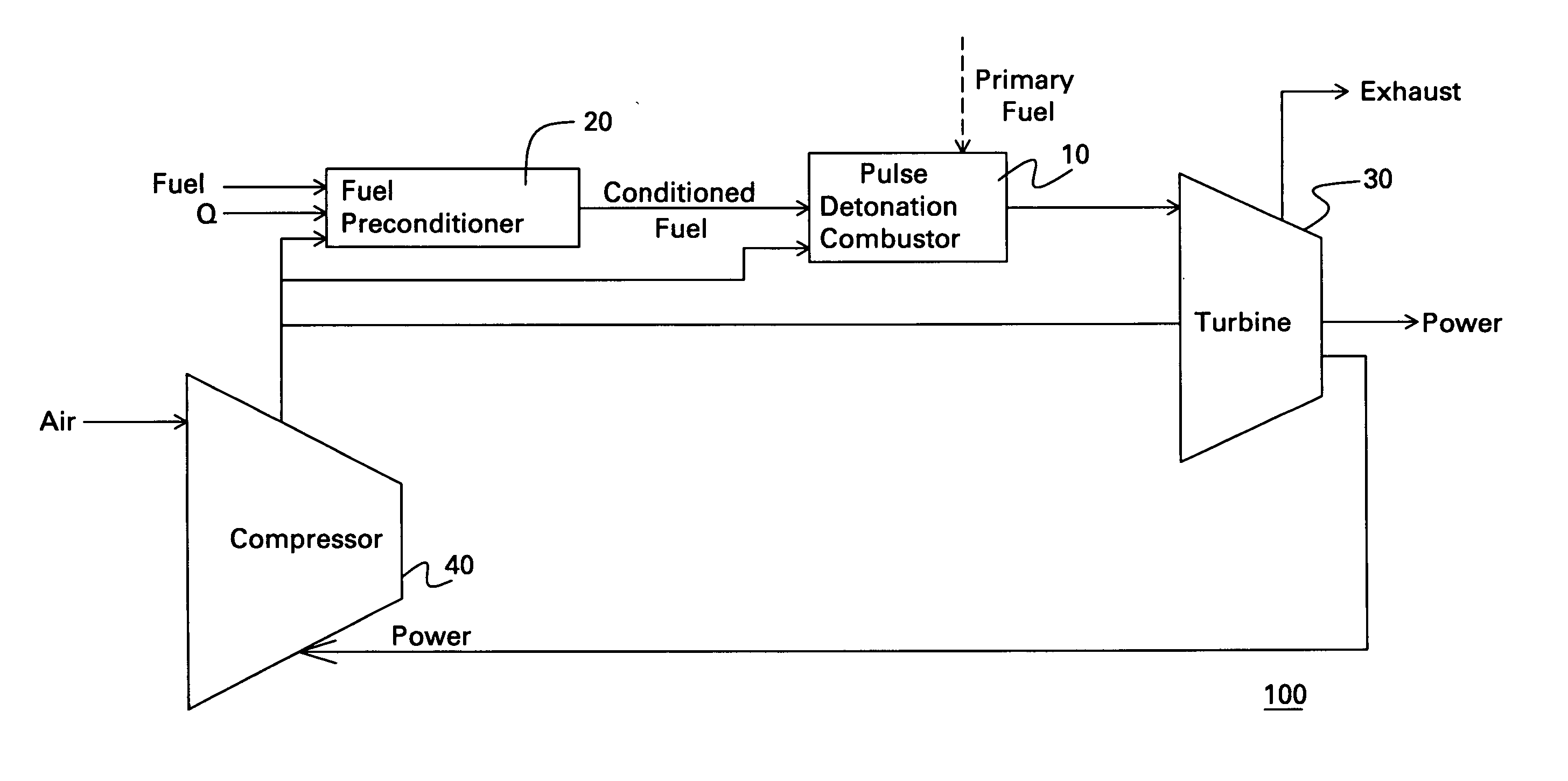
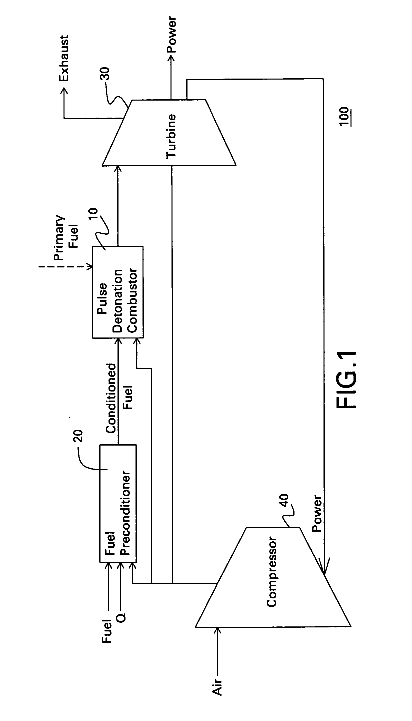
[0019] A first embodiment is described with respect to FIG. 1. As shown, the power system 100 includes a fuel preconditioner 20, which is adapted to convert a fuel to at least one conditioned fuel. The “Q” in FIG. 1 indicates the addition of energy to the preconditioner 20 via combustion / partial oxidation, electrical power, and / or heat. The power system 100 further includes a pulse detonation combustor 10, which is adapted to receive the conditioned fuel and a primary oxidizer, to detonate a mixture comprising the conditioned fuel and the primary oxidizer and to exhaust a number of detonation products. Exemplary oxidizers include air and compressed air. The power system 100 further includes a turbine 30 positioned downstream from the pulse detonation combustor 10 and in flow communication with the pulse detonation combustor 10.

[0020] As used herein, a “pulse detonation combustor” (or pulse detonation engine) is understood to mean any device or system that produces both a pressure r...


PUM


Abstract

A power system includes a fuel preconditioner adapted to convert a fuel to at least one conditioned fuel, a pulse detonation combustor, and a turbine. The pulse detonation combustor is adapted to receive the conditioned fuel and a primary oxidizer and to detonate a mixture including the conditioned fuel and the primary oxidizer and exhaust a number of detonation products. The turbine is positioned downstream from and in flow communication with the pulse detonation combustor. A power plant includes at least one fuel preconditioner and a number of power systems. Each power system includes a pulse detonation combustor and a turbine positioned downstream from and in flow communication with the pulse detonation combustor.

Description

BACKGROUND OF THE INVENTION [0001] The invention relates generally to simple and combined cycle power systems and, more particularly, to simple and combined cycle power systems using pulse detonations. [0002] A primary objective in power system design is increased efficiency, for both simple cycle and combined cycle systems. However, to achieve high cycle efficiencies, both the pressure ratio and the working temperature must be as high as materials and cooling technology permit. Presently, high-pressure ratios are achieved using complex high-pressure compressors and turbines, which help to compensate for the four to seven percent (4-7%) pressure loss that results from conventional combustion processes. However, these systems involve numerous pieces of complex rotating machinery. [0003] Recently, efforts have begun to explore the use of pulse detonation engines in aircraft engines. Beneficially, pulse detonation engines produce a pressure rise from a series of repeating detonations. ...

Claims


Application Information

Patent Timeline
IPC IPC(8): F02C3/24F01K23/10F02C3/28F02C5/02F02C5/11F23R7/00
CPCF02C5/11Y02E20/16Y02E20/18
Inventor DEAN, ANTHONY JOHNLEYVA, IVETT ALEJANDRA
Owner GENERAL ELECTRIC CO
Why Eureka
Try Eureka