Method for operating a gas turbine group

a gas turbine and group technology, applied in the direction of engines, machines/engines, mechanical apparatus, etc., can solve the problems of increasing the overall mass flow, increasing the combustion temperature, and increasing the wear of critical parts that are critical to service life, so as to increase the mass flow upstream, reduce the compressor outlet temperature, and increase the power

Inactive Publication Date: 2005-05-26
ANSALDO ENERGIA IP UK LTD
View PDF64 Cites 36 Cited by
  • Summary
  • Abstract
  • Description
  • Claims
  • Application Information

AI Technical Summary

Benefits of technology

[0016] It is known to increase the power by injecting, for example, water and / or steam and / or another suitable medium, such as CO2 or another gas, which may be produced during chemical processes, in order to increase the mass flow upstream of and / or in and / or immediately downstream of the heat supply component, i.e. in general a combustion chamber, into at least part of the compressed intake air or of the hot combustion air. Injection into the combustion chamber usually leads to an increase in the compressor outlet temperature. The additional cooling of the intake air or the additional intercooling reduces the compressor outlet temperature and therefore widens the operating range in which the injection of steam can be used to increase power. Without this combination with the cooling of the working medium before and / or during the compression, there are likely to be limits on the injection into or downstream of the combustion chamber at high ambient temperatures, when the power of the gas turbine power plant is anyway lower and the demand for power is highest for most applications. Therefore, the cooling of the working medium before and / or during the compression may be combined with the described introduction of an additional medium. The introduction of the additional medium, which is generally an inert medium, is effected, for example, by the supply of cooling air for the first row of guide vanes into the hot-gas path, the medium being supplied, for example, via a line that is provided with an actuator and opens out into an annular space for cooling air, with the additional medium then being passed via a cooling air-opening through the heat shield onto the guide vanes of the first turbine guide vane row. Alternatively, or at the same time, it is possible to configure the injection in such a way that it injects additional medium via the cooling-air supply for the blades of the first turbine rotor blade row into the combustion-air path. In principle, injection downstream of the combustion chamber provides the advantage that the injection not only increases the mass flow at the turbine inlet, but also produces an advantageous cooling action. Furthermore, larger quantities of inert medium cannot always be injected into the combustion chamber without problems. In particular, if an inert medium is injected directly into the combustion chamber, this can disrupt combustion, resulting in increased emissions or unstable combustion. The supply of steam to the first guide vane row or to the first turbine rotor blade row furthermore has the advantage that on account of the additional use of steam in the normal cooling-air path, these blades, which are actually designed for air cooling, are cooled to a greater extent than necessary on account of the higher heat capacity and the good heat transfer to steam. Consequently, it then becomes possible potentially to increase the firing temperature further, with the result that the power potentials that can be opened up beyond the actual nominal power of the gas turbine group are additionally increased.
[0017] As a result of the control in accordance with the invention, the gas turbine group is at any time operated optimally, i.e. the use of power-increasing measures is optimized for the overall process, and the wear is thereby minimized, and the consumption of fuel, the cooling power and, if appropriate a consumption of coolant, as well as the consumption of steam and / or water that may have been injected, is likewise reduced to the minimum required at any particular time.

Problems solved by technology

The prior art in this context is a simple “on / off function”, but with all known methods it is typical to expect an increase in the wear to parts that are critical to service life.
Moreover, the injection of water leads to an increase in the overall mass flow.
One problem with this procedure is the fact that the injection of water upstream of the compressor leads to a change in the combustion temperature in the combustion chamber, and accordingly stability problems may arise as a result of the procedure described in this document.
Furthermore, it must be noted that according to the procedure disclosed in U.S. Pat. No. 6,216,443, it is impossible to ensure that the machine will actually operate at its nominal full load and therefore generally at its optimum efficiency.
Both of these problems are harmful to the gas turbine efficiency.

Method used


Image

  • Method for operating a gas turbine group
  • Method for operating a gas turbine group
  • Method for operating a gas turbine group

Examples


Embodiment Construction

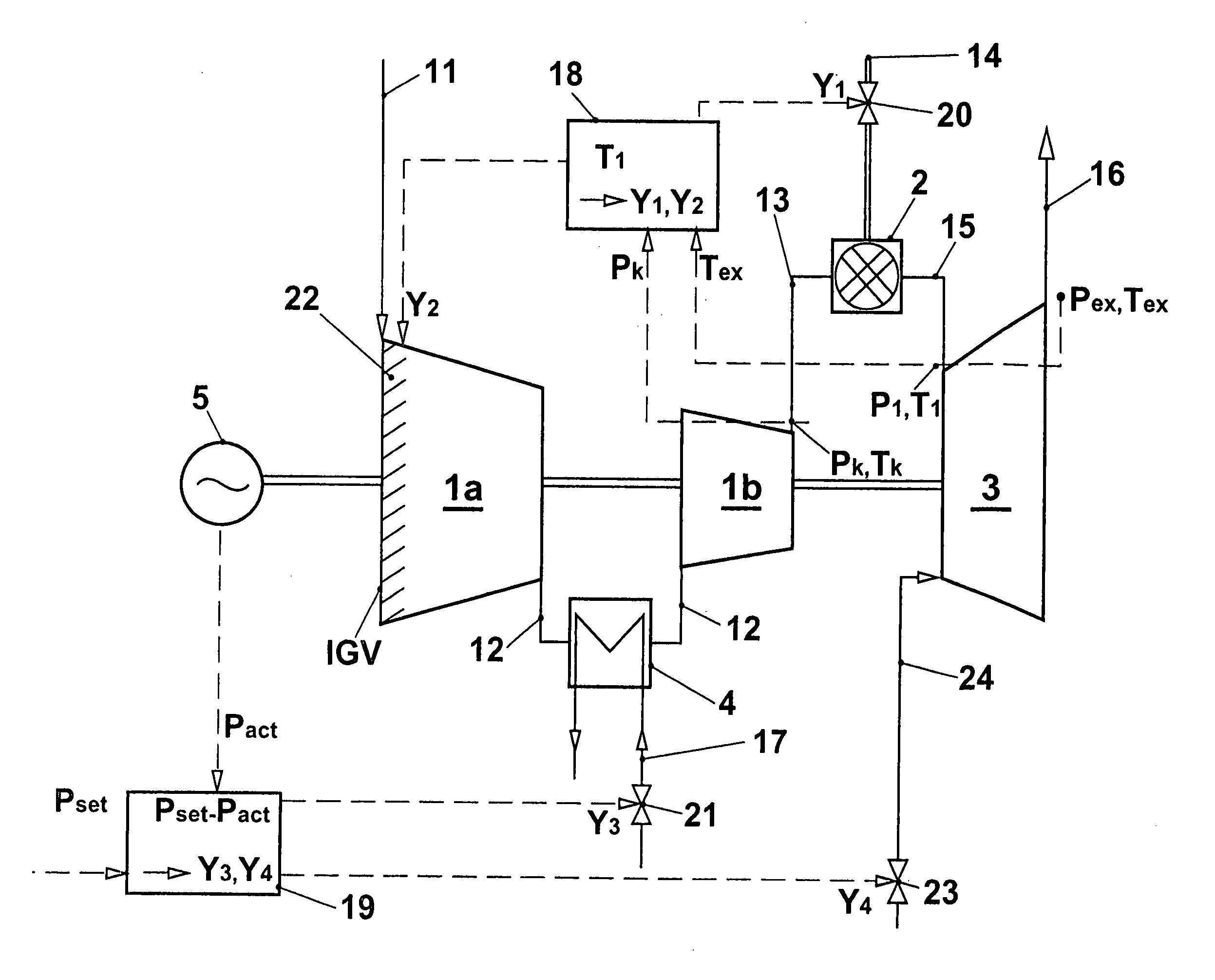
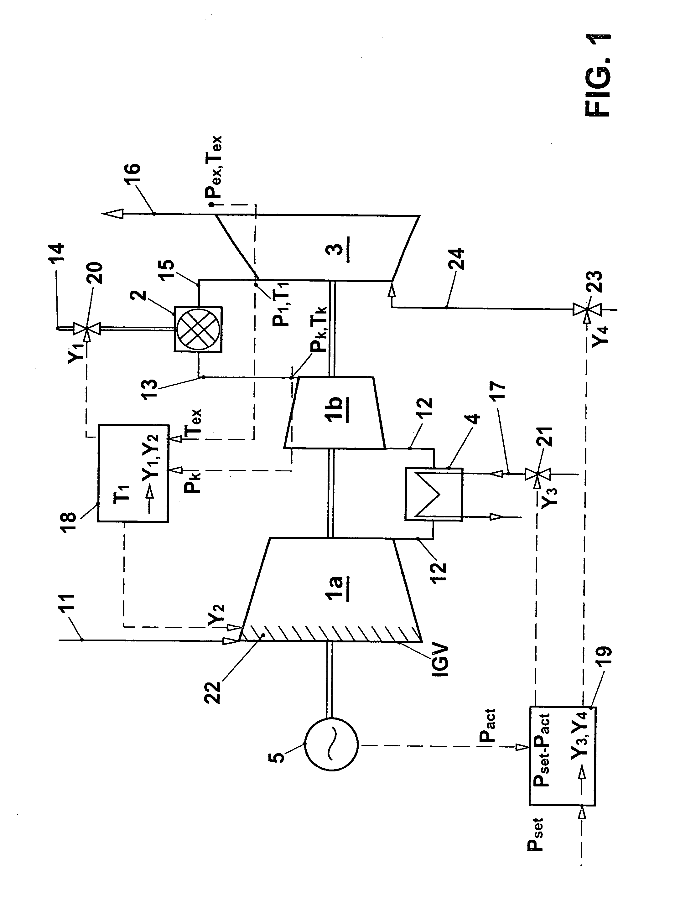
[0027]FIG. 1 shows a gas turbine installation for carrying out a method according to the invention. A compressor 1 comprising a first partial compressor 1a and a second partial compressor 1b, sucks in a quantity of air 11 as working medium for the gas turbine group. This quantity of air is compressed to a first pressure in the first partial compressor 1a, then the partially compressed air 12 flows through a cooling apparatus 4 designed as a heat exchanger and then into the second partial compressor 1b, where the air is compressed further. Compressed working medium 13 flows into a combustion chamber 2 at a pressure pk and a temperature Tk. In the combustion chamber 2, a quantity of fuel 14 is supplied and burnt. Hot gas 15 at a temperature T1 and a pressure p1 flows into the turbine 3, where it is expanded, delivering a useful power, before flowing out as expanded exhaust gas 16 at a temperature Tex and a pressure pex which substantially corresponds to atmospheric pressure. The consi...


PUM


Abstract

A gas turbine group is provided with at least one cooling apparatus for cooling the working medium before and/or during the compression. The cooling power of the cooling apparatus can be adjusted by suitable means. A controller controls the cooling power of the cooling apparatus as a function of a control deviation in the useful power of the gas turbine group. The cooling controller interacts with other controllers of the gas turbine group in such a way that the gas turbine group is itself always operated at least close to its full load operating state. In this context, it is preferable for the inlet guide vane row of the compressor to be maximally open, and for the hot-gas temperature on entry into the turbines to be controlled so that it is constantly at an upper limit value.

Description

CROSS-REFERENCE TO RELATED APPLICATIONS [0001] This application is a continuation of the U.S. National Stage designation of co-pending International Patent Application PCT / CH02 / 00709 filed Dec. 17, 2002, the entire content of which is expressly incorporated herein by reference thereto.FIELD OF THE INVENTION [0002] The present invention relates to a method for operating a gas turbine group. BACKGROUND OF THE INVENTION [0003] In today's deregulated energy markets, covering peak load demand and the rapid provision of reserves of power has become a lucrative source of income for power plant operators. A number of methods for increasing power, such as the injection of water or steam in the combustion chamber, cooling or intercooling of the inlet air or injection of water into the compressor, are known measures for covering peak loads. The prior art in this context is a simple “on / off function”, but with all known methods it is typical to expect an increase in the wear to parts that are c...

Claims


Application Information

Patent Timeline
Patent Type & Authority Applications(United States)
IPC IPC(8): F02C7/141F02C7/143F02C9/00F02C9/20F02C9/26F02C9/28
CPCF02C7/141F02C7/1435F02C9/20F05D2260/212F02C9/28F05D2260/211F02C9/26
Inventor BRAUN, JOSTHOFFMANN, JURGENMOLLER, UWE
Owner ANSALDO ENERGIA IP UK LTD
Why Eureka
Try Eureka