Photoelectric conversion apparatus and image pickup system using photoelectric conversion apparatus

a technology of photoelectric conversion and photoelectric converter, which is applied in the direction of optical radiation measurement, radiation control devices, instruments, etc., can solve the problems of film thickness, film thickness, film production, etc., and achieve good color reproducibility

Inactive Publication Date: 2005-05-26
CANON KK
View PDF11 Cites 32 Cited by
  • Summary
  • Abstract
  • Description
  • Claims
  • Application Information

AI Technical Summary

Benefits of technology

[0013] According to the present invention, no differences of color ratios between B/G and R/G are produced even when film thicknesses of antireflective

Problems solved by technology

However, the present inventor found that there was a problem that the variation of the film thicknesses of the antireflective films and the variation of the film thicknesses of the insulation films were produced owing to the variation of the film thicknesses at processing processes a

Method used


Image

  • Photoelectric conversion apparatus and image pickup system using photoelectric conversion apparatus
  • Photoelectric conversion apparatus and image pickup system using photoelectric conversion apparatus
  • Photoelectric conversion apparatus and image pickup system using photoelectric conversion apparatus

Examples


example 1

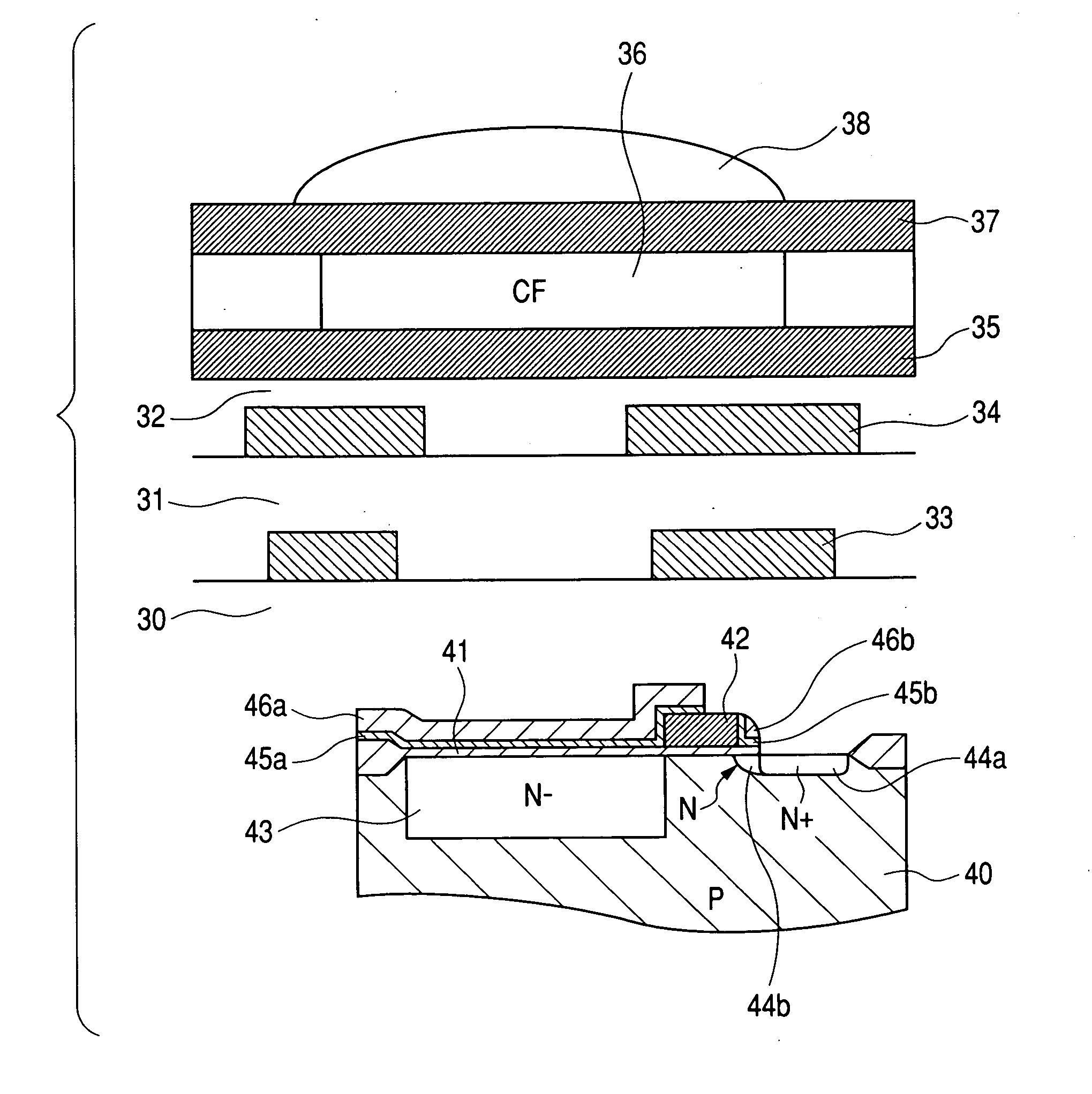
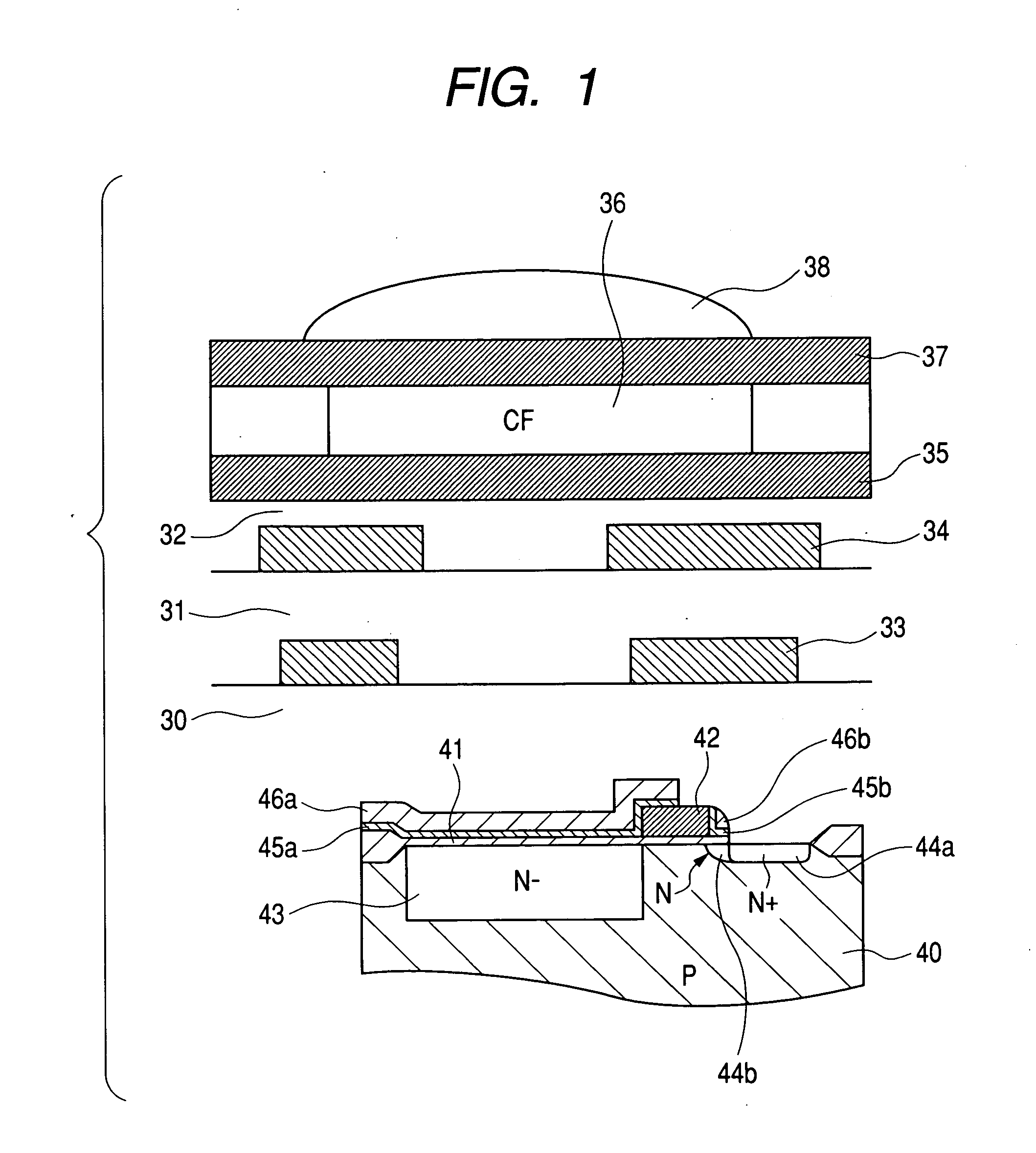
[0036] In accordance with claim 1 of the present invention, after the insulation film of the photoelectric conversion apparatus of FIG. 1 was formed to be 8 nm thick as a silicon oxide film and the antireflective film was formed to be 30 nm thick as a silicon nitride film, wiring layers were formed. Thereby, a photoelectric conversion apparatus including formed color filter layers of red, green and blue was made. The present example was made to have a variation in the antireflective film. FIG. 5 shows a spectral characteristic of the present example. A reference numeral 101 denotes a spectral characteristic in the case where the antireflective film takes a designed value (30 nm). A reference numeral 102 denotes a spectral characteristic in the case where the antireflective film is thicker by 10% (33 nm) owing to a variation. A reference numeral 103 denotes a spectral characteristic in the case where the antireflective film is thinner by 10% (27 nm) owing to a variation. A reference ...

example 2

[0040] In accordance with claim 1 of the present invention, after the insulation film of the photoelectric conversion apparatus of FIG. 1 was formed to be 8 nm thick as a silicon oxide film and the antireflective film was formed to be 30 nm thick as a silicon nitride film, wiring layers were formed. Thereby, a photoelectric conversion apparatus including formed color filter layers of red, green and blue was made. The present example was made to have a variation in the antireflective film. FIG. 6 shows a spectral characteristic of the present example. A reference numeral 201 denotes a spectral characteristic in the case where the antireflective film takes a designed value (8 nm) . A reference numeral 202 denotes a spectral characteristic in the case where the antireflective film is thicker by 10% owing to a variation. A reference numeral 203 denotes a spectral characteristic in the case where the antireflective film is thinner by 10% owing to a variation. A reference numeral 204 deno...

example 3

[0044] In accordance with claim 1 of the present invention, the insulation film of the photoelectric conversion apparatus of FIG. 1 was formed to be 8 nm thick as a silicon oxide film (n=1.66), and the antireflective film was formed to be 50 nm thick as a silicon oxynitride film. After that, wiring layers were formed. Thereby, a photoelectric conversion apparatus including formed color filter layers of red, green and blue was made. The present example was made to have variations in the antireflective film and in the insulation film. FIG. 7 shows spectral characteristics of the present example. A reference numeral 301 denotes a spectral characteristic in the case where the antireflective film takes a designed value. A reference numeral 302 denotes a spectral characteristic in the case where the antireflective film and the insulation film are severally thicker by 10% owing to a variation. A reference numeral 303 denotes a spectral characteristic in the case where the antireflective fi...


PUM


Abstract

It is a main object of the present invention to suppress the differences of color ratios of B/G and R/G when the film thicknesses of antireflective films and insulation films vary at a processing process. The present invention is a photoelectric conversion apparatus including a plurality of light receiving portions arranged on a semiconductor substrate, antireflective films formed on the light receiving portions with insulation films put between them, and color filter layers of a plurality of colors formed on the antireflective films, wherein film thicknesses of the insulation films and/or the antireflective films are changed such that changing directions of spectral transmittances at peak wavelengths of color filters on sides of the shortest wavelengths and at peak wavelengths of color filters on sides of the longest wavelengths after transmission of infrared cutting filters may be the same before and after changes.

Description

BACKGROUND OF THE INVENTION [0001] 1. Field of the Invention [0002] The present invention relates to a photoelectric conversion apparatus and an image pickup system, and more particularly to a photoelectric conversion apparatus and an image pickup system both of which include a plurality of light receiving portions arrange on a semiconductor substrate, an antireflective film formed above the light receiving portions with an insulation film put between them, and color filter layers of a plurality of colors formed on the antireflective film. [0003] 2. Description of Related Art [0004] As a solid state image pickup device, a charge coupled device (CCD) type photoelectric conversion element has conventionally been used in many cases. However, a complementary metal oxide semiconductor (CMOS) type photoelectric conversion element has been reconsidered recently, and a trend of commercialization of product of the CMOS type photoelectric conversion element has been generated owing to the mer...

Claims


Application Information

Patent Timeline
IPC IPC(8): H01L27/146H01L29/06H01L31/0216H01L31/0328H01L27/14H01L31/0336H01L31/072H01L31/10H04N5/335H04N5/369H04N101/00
CPCH01L27/14609H01L27/1462H01L27/14621H01L31/02162H01L27/14627H01L27/14643H01L31/02161H01L27/14625
Inventor NODA, TOMOYUKI
Owner CANON KK
Why Eureka
Try Eureka