Method for operating a laser scanning confocal microscope system and a system thereof

a microscope system technology, applied in the direction of luminescent dosimeters, optical radiation measurement, fluorescence/phosphorescence, etc., can solve the problems of inability to control, lack of flexibility, and difficulty in controlling so as to achieve easy and easy modification of the control of laser scanning confocal microscopes, simple and flexible control, the effect of simple and effective control

Inactive Publication Date: 2005-05-26
UNIVERSITY OF ROCHESTER
View PDF12 Cites 8 Cited by
  • Summary
  • Abstract
  • Description
  • Claims
  • Application Information

AI Technical Summary

Benefits of technology

[0007] The present invention provides a method and system for simple and flexible control of a laser scanning confocal microscope. More specifically, the present invention provides simple and effective controls over aspects of the laser scanning confocal microscope system, such as the front panel user interface, the synchronization of beam deflection device movement and photomultiplier tube data acquisition, as well the display, processing, and storage of images. With the present invention, control of the laser scanning confocal microscope can be readily and easily modified for specific applications and also for interfacing with other instruments.

Problems solved by technology

Unfortunately, control of laser scanning confocal microscopes has been fairly difficult and rigid.
As a result, an operator of a laser scanning confocal microscope must spend a great deal of time and effort to modify the operation of a laser scanning confocal microscope for particular application.
Additionally, there have been some deficiencies in controlling the timing of different operations within the laser scanning confocal microscope.

Method used


Image

  • Method for operating a laser scanning confocal microscope system and a system thereof
  • Method for operating a laser scanning confocal microscope system and a system thereof
  • Method for operating a laser scanning confocal microscope system and a system thereof

Examples


Embodiment Construction

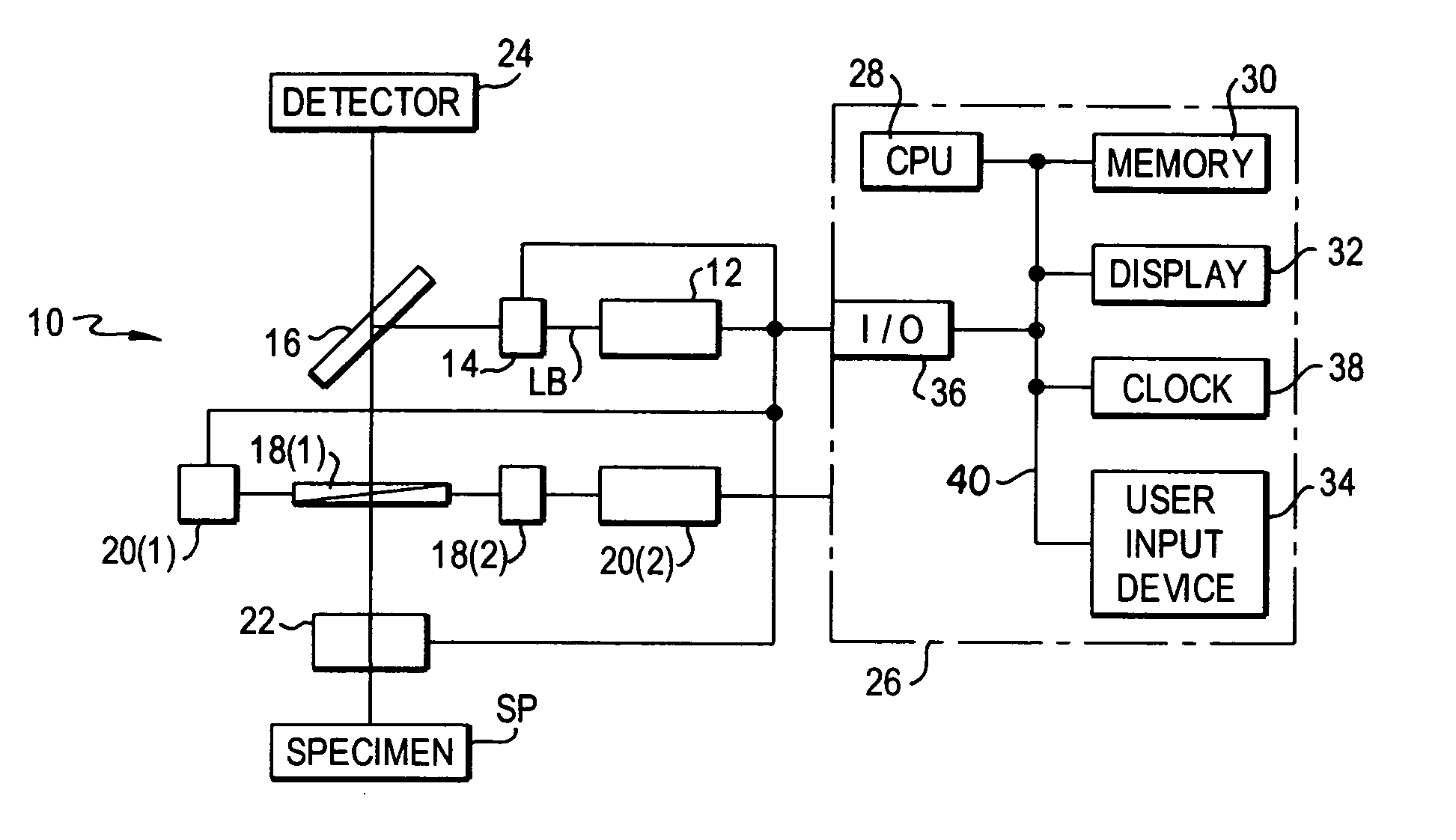
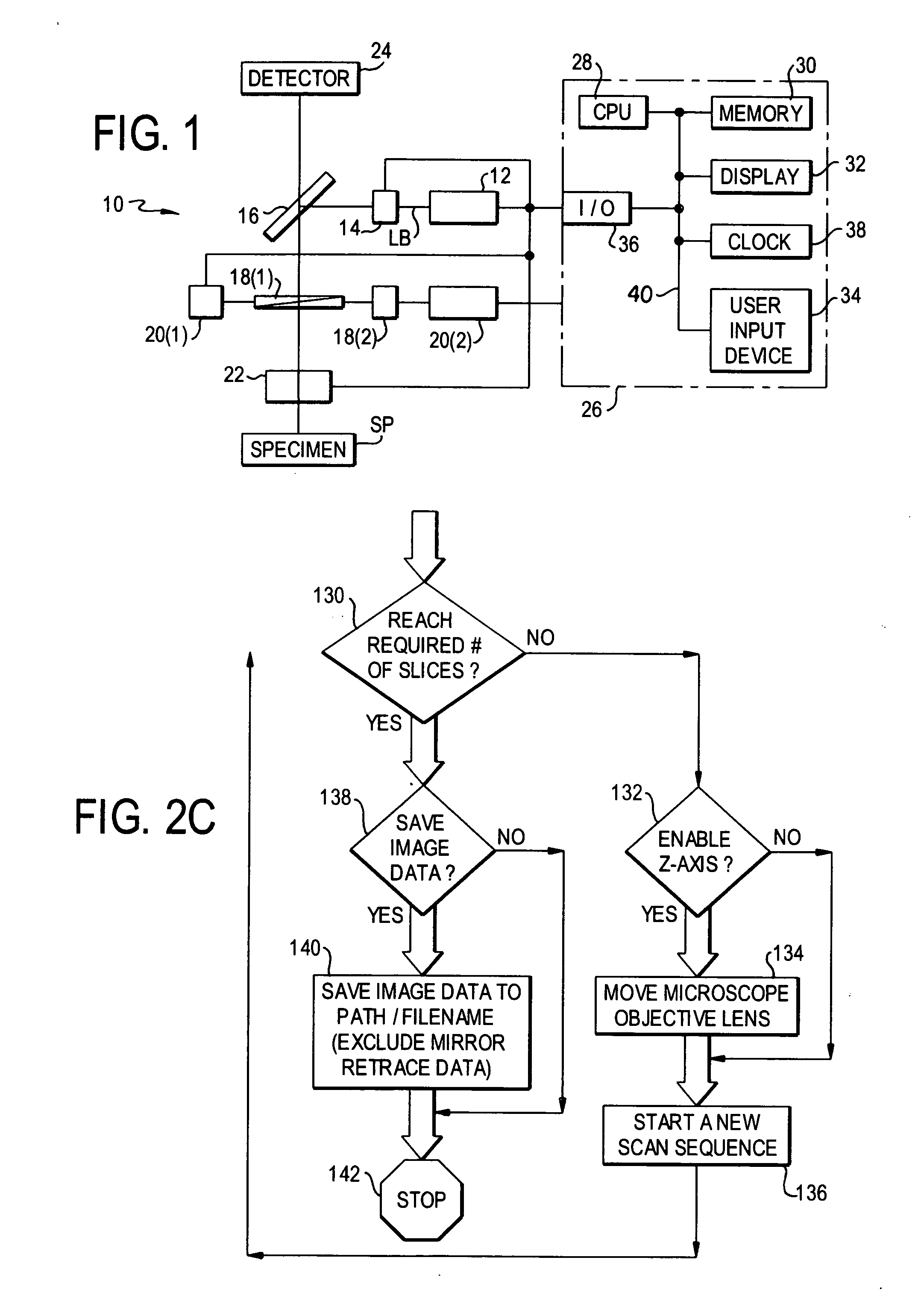
[0011] A system and method for operating a laser scanning confocal microscope system 10 in accordance with embodiments of the present invention is illustrated in FIGS. 1 and 2A-2C. The system 10 includes a laser source 12, a shutter 14, a beam splitter 16, mirrors 18(1) and 18(2), stepper motor systems 20(1) and 20(2) 20(1) and 20(2), an objective lens system 22, a photomultiplier tube 24, and scanning control system 26 although other types and number of components could be used. The present invention provides a number of advantages including providing simple and flexible control of a laser scanning confocal microscope 10.

[0012] Referring to FIG. 1, the laser source 12 generates a laser beam LB which is used in scanning a specimen SP or other sample. The laser source 12 is coupled to the scanning control system 26 which controls operations of the laser source 12, such as when the laser source 12 is engaged to generate a light beam and the type of light beam generated by the laser s...


PUM

PropertyMeasurementUnit
confocal spectraaaaaaaaaaa
depthaaaaaaaaaa
fluorescentaaaaaaaaaa

Abstract

A method for operating a confocal microscope system includes deflecting a light beam on a specimen with at least one beam deflection device. The position of the light beam is stepped with at least one beam deflection device across the specimen. A sample of emitted fluorescent light from the specimen is captured in synchronization with each of the stepped positions of the light beam. An image is obtained from the captured samples of emitted fluorescent light.

Description

[0001] This application claims the benefit of U.S. Provisional Patent Application Ser. No. 60 / 307,243 filed Jul. 23, 2001 which is hereby incorporated by reference in its entirety.FIELD OF THE INVENTION [0002] This invention relates to a method for operating a confocal microscope system and a system thereof. BACKGROUND OF THE INVENTION [0003] Laser scanning confocal microscopes have the ability to penetrate beneath the surface of a specimen to obtain slices of imaging data. These slices or sections can be taken at specific depths in the specimen and then can be re-combined to form a three dimensional image of the examined section. In order to be viewed by the laser scanning confocal microscope, the section of the specimen being examined must be auto-fluorescent or be stained with fluorescent dyes. [0004] Unfortunately, control of laser scanning confocal microscopes has been fairly difficult and rigid. As a result, an operator of a laser scanning confocal microscope must spend a grea...

Claims


Application Information

Patent Timeline
Patent Type & Authority Applications(United States)
IPC IPC(8): G02B21/00
CPCG02B21/0076G02B21/0024
Inventor FOSTER, THOMAS H.CONOVER, DAVID L.BIGLOW, CHAD E.GEORGAKOUDI, IRENEMEZHIBA, ANDREYMITRA, SOUMYA
Owner UNIVERSITY OF ROCHESTER
Why Eureka
Try Eureka