Catoptric and catadioptric imaging system with pellicle and aperture-array beam-splitters and non-adaptive and adaptive catoptric surfaces

a technology of pellicle aperture and aperture array, applied in the direction of optical radiation measurement, instruments, interferometers, etc., can solve the problem of introducing the possibility of non-common path phase error

Inactive Publication Date: 2005-05-26
ZETETIC INST
View PDF50 Cites 24 Cited by
  • Summary
  • Abstract
  • Description
  • Claims
  • Application Information

AI Technical Summary

Benefits of technology

[0013] When the shorter wavelength beam has a wavelength in the UV, VUV, or EUV and a thin fluorescent layer serves the beam combining function, there is a significant change in the required performance of the detector because it has to serve to only detect the longer wavelength optical beam instead of the shorter wavelength mixed beam. The advantage of the present invention with respect to the reduction on the required performance specifications of the optical elements and the detector is valid for measurement and reference beams comprising either UV, VUV, or EUV wavelengths.
[0014] The implementation of the N-dimensional bi- and quad-homodyne detection methods make it possible to extend the advantages of the bi- and quad-homodyne detection methods for measuring conjugated quadratures of fields jointly to homodyne methods for measuring conjugated quadratures of fields when measuring jointly N different properties of the fields.
[0015] In general, in one aspect, the invention features an interferometric system including: an interferometer that directs a measurement beam at an object point to produce a return measurement beam, focuses the return measurement beam to an image point in an image plane, and mixes the return measurement beam with a reference beam at the image point to form a mixed beam; a beam combining layer located at the image plane which is responsive to the mixed beam and produces an optical beam therefrom, wherein the layer includes a thin film with an array of transmissive openings formed therein and further includes a fluorescent material associated with each of the openings of the array of openings; a detector that is responsive to the optical beam from the beam combining layer; and an imaging system that directs the optical beam from the beam combining layer onto the detector.
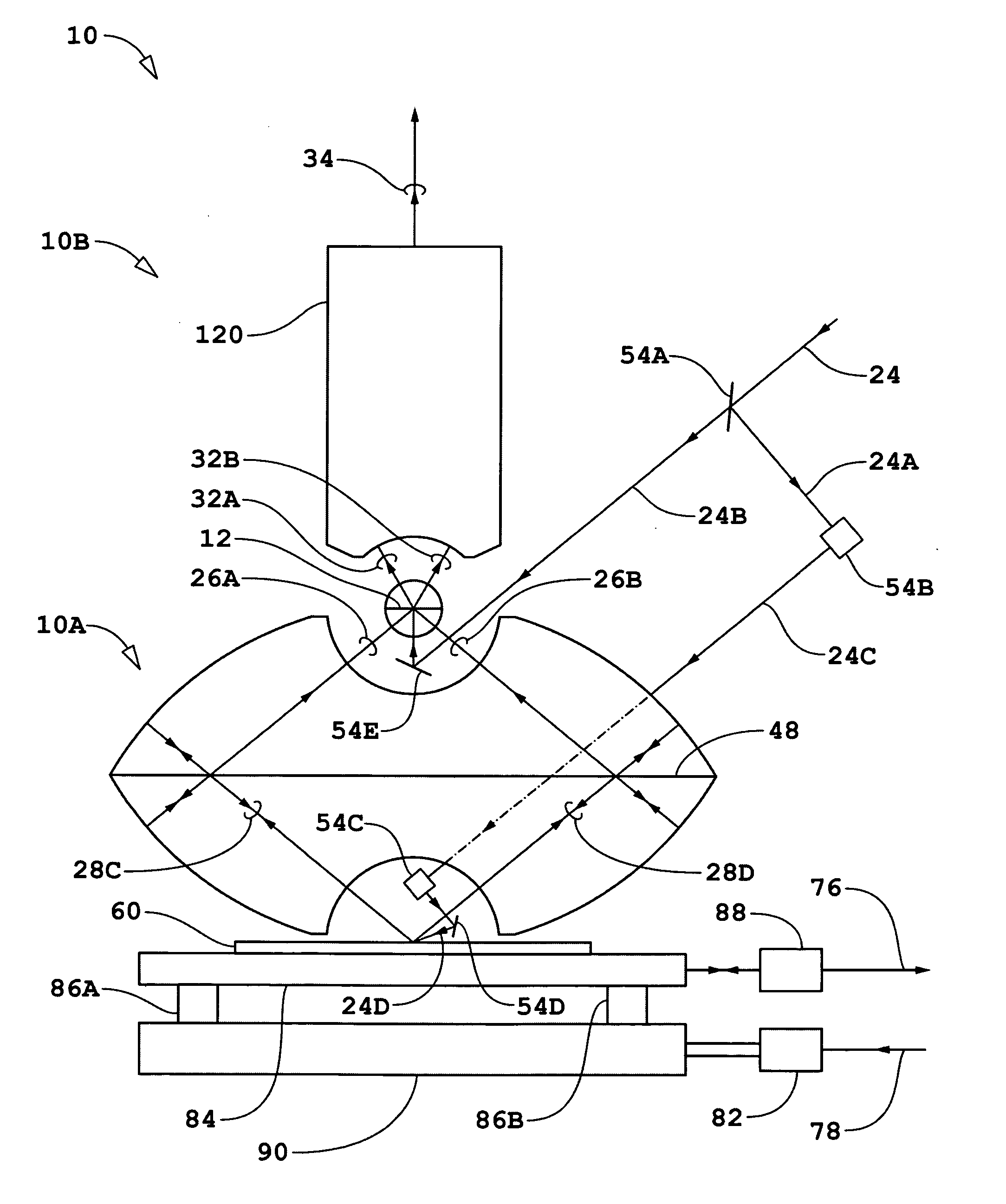
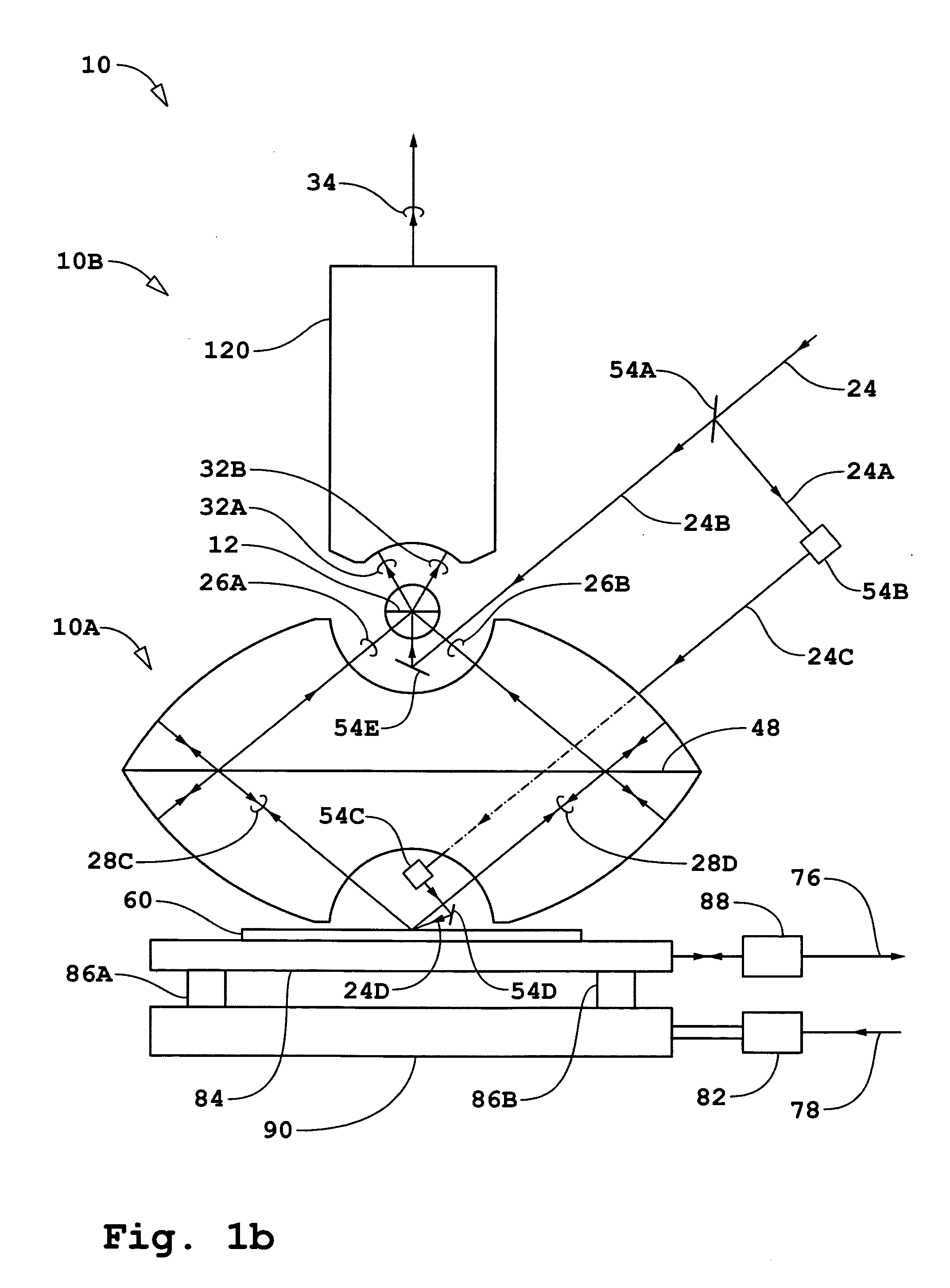
[0016] Other embodiments include one or more of the following features. The beam combining layer includes a first layer in which the array of openings is formed and a second layer behind the first layer and includes the fluorescent material. The beam combining layer further includes a third layer including an array of microlenses, each of which is aligned with a different one of the openings in the array of openings. Alternatively, the fluorescent material is in each of the openings of the array of openings. Each of the openings in the array of openings is conically shaped. The fluorescent material is lumogen. The fluorescent material is sensitive to UV or VUV. The fluorescent material is responsive to radiation at a first wavelength and the detector is responsive to light at a second wavelength, wherein the first and second wavelengths are different. The fluorescent material is responsive to radiation in the UV or VUV region and the detector is responsive to light in the visible region. The fluorescent material absorbs radiation at a first wavelength and emits radiation at a second wavelength, wherein the second wavelength is longer than the first wavelength. The imaging system is a low power microscope. The interferometer includes a catadioptric imaging system. The interferometer includes: a beam splitter positioned to receive the return measurement beam from the object point and separate each of a plurality of rays into a transmitted portion and a reflected portion, the transmitted portions defining a first set of rays and the reflected portions defining a second set of rays; and a reflecting surface positioned to receive one of the sets of rays from the beam splitter and focus that set of rays towards the image point via the beam splitter. The beam splitter has an array of transmitting apertures formed therein and wherein the one set of rays travels along a path contacting on one end the beam splitter and on another end the concave reflecting surface and at least most of which passes through a gas or vacuum. The interferometer includes an array of independently positionable reflecting elements forming the reflecting surface. The reflecting surface is positioned to receive the first set of rays and reflect the first set of rays back to the beam splitter, and wherein the beam splitter is positioned to reflect at least a portion of each ray received from the reflecting surface to the image point.
[0017] In general, in another aspect, the invention features an imaging system for imaging an object point to an image point, the system including: a beam splitter positioned to receive light rays from the object point and separate each of a plurality of rays into a transmitted portion and a reflected portion, the transmitted portions defining a first set of rays and the reflected portions defining a second set of rays; and an optical structure forming a concave reflecting surface positioned to receive one of the sets of rays from the beam splitter and focus that set of rays towards the image point via the beam splitter, wherein the beam splitter has an array of transmitting apertures formed therein and wherein the one set of rays travels along a path contacting on one end the beam splitter and on another end the concave reflecting surface and at least most of which passes through a gas or vacuum.
[0018] Other embodiments include one or more of the following features. The beam splitter is a self-supporting structure. The beam splitter includes a thin reflective layer in which the array of transmitting apertures are formed. The thin reflective layer is highly reflective. The thin reflective layer is made of aluminum. The beam splitter includes a pellicle on which the thin reflective layer is formed. The beam splitter includes a first pellicle and a second pellicle with the thin reflective layer sandwiched between the first and second pellicles. The pellicle is made of a refractive material, e.g. UV grade fused silica, F—SiO2, CaF2, or LiF. The beam splitter is a vertically oriented, planar structure. The size of the apertures is larger than the wavelength of the light rays being imaged onto the image point. The beam splitter includes a grid of conducting wires which defines the array of transmitting apertures. The reflecting surface is positioned to receive the first set of rays and reflect the first set of rays back to the beam splitter, and wherein the beam splitter is positioned to reflect at least a portion of each ray received from the reflecting surface to the image point. The reflecting surface is substantially concentric with the object point. Alternatively, the reflecting surface is positioned to receive the second set of rays and reflect the second set of rays back to the beam splitter, wherein the beam splitter is positioned to transmit at least a portion of each ray received from the reflecting surface to the image point. In that case, the reflecting surface is substantially concentric with the image point. The optical structure includes an array of independently positionable reflecting elements forming the reflecting surface.

Problems solved by technology

In the case where a beam-splitter is used for the beam combining function, the measurement beam component and the reference beam component of the combined beam may have subsequent to the beam-splitter different paths in the optical elements which introduces the possibility of non-common path phase errors.

Method used


Image

  • Catoptric and catadioptric imaging system with pellicle and aperture-array beam-splitters and non-adaptive and adaptive catoptric surfaces
  • Catoptric and catadioptric imaging system with pellicle and aperture-array beam-splitters and non-adaptive and adaptive catoptric surfaces
  • Catoptric and catadioptric imaging system with pellicle and aperture-array beam-splitters and non-adaptive and adaptive catoptric surfaces

Examples


first embodiment

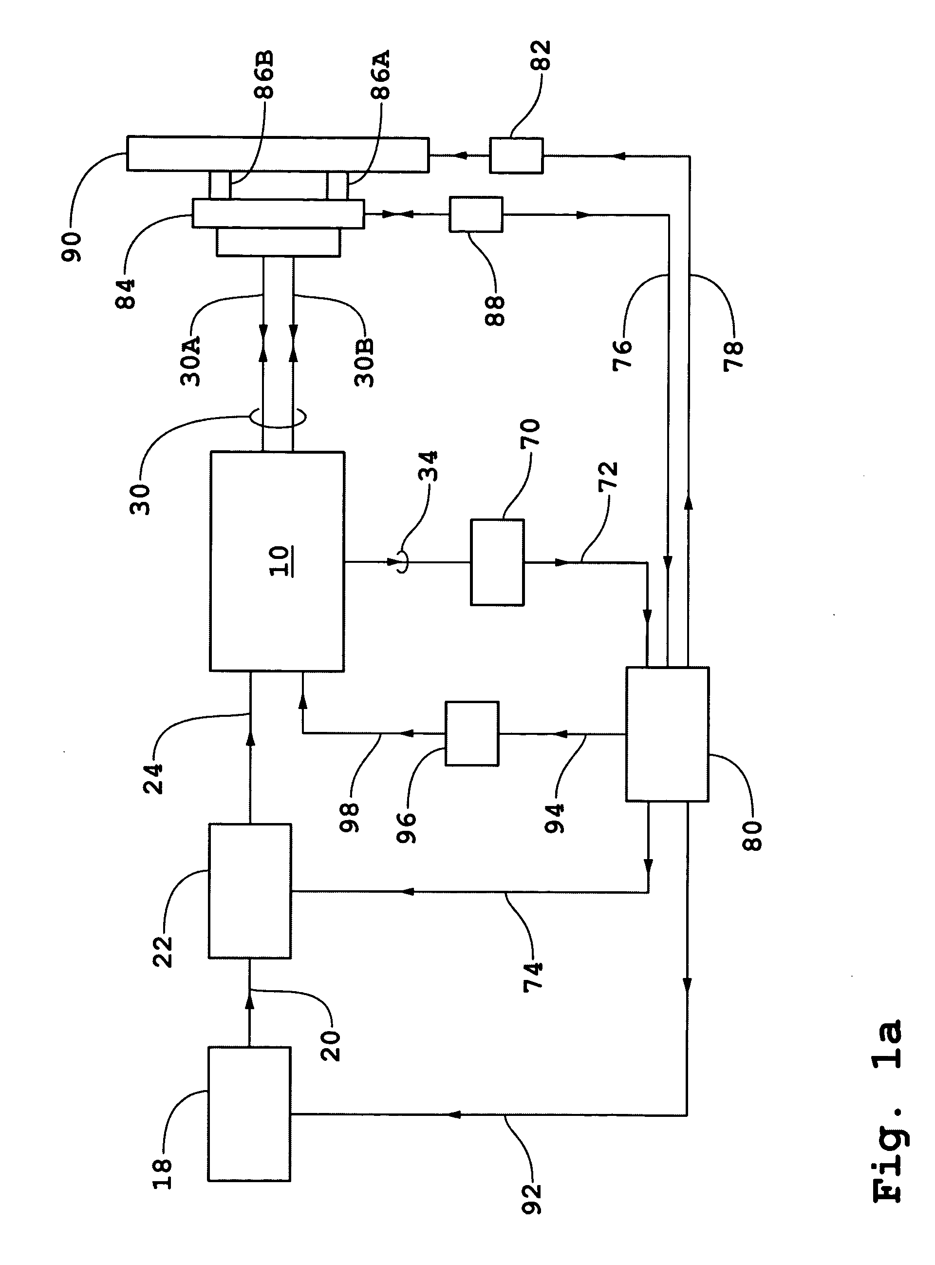
[0102] Adaptive reflecting surfaces 42A-1, 42A-2, 42A-3, 42C-1, 42C-2, and 42C-3 and adaptive reflecting surfaces 46A-1, 46A-2, 46C-1, and 46C-2 shown in FIG. 1c may each be representative of annular rings or of sections of annular rings. The remaining description of the first embodiment will be based on the simple configuration wherein there are no additional reflecting surfaces beyond those described as a non-limiting example without departing from the scope and spirit of the present invention. The number of corresponding adaptive reflecting surfaces defines of the values of N that may be used in the N-dimensional bi- and quad-homodyne detection methods. In the non-limiting example of the simple configuration shown in FIG. 1c, the maximum value for N is 6.

[0103] Referring to FIG. 1d, the locations and orientations of adaptive reflecting surfaces are controlled by transducers according to servo control signal 98 from servo controller 96. For each of the adaptive reflective surfaces...

third embodiment

[0184] The location of the object plane of catadioptric imaging system 210A may also be on the plane surface of piano convex lens 258. In this case, the measurement beam can be arranged to probe substrate 60 as an evanescent field when h is of the order of λ / 4. The third embodiment can change rapidly from using the evanescent field as a probe beam to using the non-evanescent fields as a probe beam by use of the high speed vertical scan feature of the present invention.

[0185] The fourth embodiment of the present invention comprises interferometer 10 and catadioptric imaging system 210A of the third embodiment except that thin film fluorescent layer 12 is replaced by a pinhole array beam-splitter 12 the same as in the second embodiment shown schematically in FIG. 1f. Pinhole array beam-splitter 12 is used as the beam-splitter for generating the reference and measurement beams and for the function of combining the reference and measurement beam reflected / scattered by substrate 60. The ...

fifth embodiment

[0191] Referring to FIG. 3b, mirror system 354B redirects and displaces measurement beam 324A such that measurement beam 324C is propagating in a plane displaced out of the plane of FIG. 3b. Mirror system 354C displaces measurement beam 324C such that the transmitted measurement beam subsequently reflected by mirror 354D propagates in the plane of FIG. 3b. The remaining description of the present invention is the same as corresponding descriptions given for the first four embodiments of the present invention and corresponding descriptions given for embodiments given in cited U.S. Pat. No. 6,552,852 (ZI-38) and No. 10 / 366,651 (ZI-43); U.S. Provisional Patent Applications No. 60 / 447,254 (ZI-40), No. 60 / 448,360 (ZI-41), No. 60 / 448,250 (ZI-42), No. 60 / 442,982 (ZI-45), No. 60 / 459,425 (ZI-50), No. 60 / 485,255 (ZI-53), filed Jul. 7, 2003 (ZI-52) and entitled “Apparatus and Method for High Speed Scan for Subwavelength Defects in Semiconductor Metrology,” and filed Sep. 10, 2003 (ZI-54) entit...


PUM


Abstract

An interferometric system including: an interferometer that directs a measurement beam at an object point to produce a return measurement beam, focuses the return measurement beam to an image point in an image plane, and mixes the return measurement beam with a reference beam at the image point to form a mixed beam; a beam combining layer located at the image plane which is responsive to the mixed beam and produces an optical beam therefrom, wherein the layer comprises a thin film with an array of transmissive openings formed therein and further comprises a fluorescent material associated with each of the openings of the array of openings; a detector that is responsive to the optical beam from the beam combining layer; and an imaging system that directs the optical beam from the beam combining layer onto the detector.

Description

[0001] This application claims the benefit of U.S. Provisional Application No. 60 / 506,715, filed Sep. 26, 2003.BACKGROUND OF THE INVENTION [0002] A number of different applications of catadioptric imaging systems for far-field and near-field interferometric confocal and non-confocal microscopy have been described such as in commonly owned U.S. Pat. No. 6,552,852 (ZI-38) entitled “Catoptric And Catadioptric Imaging Systems” and No. 6,717,736 (ZI-43) entitled “Catoptric And Catadioptric Imaging Systems;” U.S. Provisional Patent Applications No. 60 / 447,254, filed Feb. 13, 2003, entitled “Transverse Differential Interferometric Confocal Microscopy,” (ZI-40); No. 60 / 448,360, filed Feb. 19, 2003, entitled “Longitudinal Differential Interferometric Confocal Microscopy for Surface Profiling,” (ZI-41); No. 60 / 448,250, filed Feb. 19, 2003, entitled “Method and Apparatus for Dark Field Interferometric Confocal Microscopy,” (ZI-42); No. 60 / 442,982, filed Jan. 28, 2003, entitled “Interferometric...

Claims


Application Information

Patent Timeline
Patent Type & Authority Applications(United States)
IPC IPC(8): G01B9/02G01J1/58G02BG02B17/08G02B26/06
CPCG01J1/58G01B2290/70G01N21/9501G02B17/0808G02B17/086G02B26/06G03F1/84G03F7/7085G03F9/7088G01B9/02079G01B9/02007G01B9/02056G01B9/02014G01B9/02022G01B9/02068G01N21/8806
Inventor HILL, HENRY A.HAMANN, STEVENFISCHER, DAVID A.
Owner ZETETIC INST
Why Eureka
Try Eureka