Electro-optical device and electronic apparatus

a technology of optical devices and electronic devices, applied in piezoelectric/electrostrictive transducers, identification means, instruments, etc., can solve the problems of inability to achieve satisfactory reduction in inability to increase enclosure thickness, and inability to increase the size or thickness of enclosures

Active Publication Date: 2005-05-26
BOE TECH GRP CO LTD
View PDF2 Cites 10 Cited by
  • Summary
  • Abstract
  • Description
  • Claims
  • Application Information

AI Technical Summary

Benefits of technology

[0008] In order to solve the aforementioned problem, it is an object of the present invention to provide an electro-optical device with a sound generating body, in which the electro-optical device and the sound generating body can be mounted compactly. A...

Problems solved by technology

Therefore, with the structure in the related art, if a display unit and a sound generating unit are disposed one on another, the thickness of the enclosure is inevitably increased and, if attempt is made to avoid increase in thickness of the enclosure, it is necessary to dispose the display unit and the sound generating unit so as to avoid overlapping, an...

Method used


Image

  • Electro-optical device and electronic apparatus
  • Electro-optical device and electronic apparatus
  • Electro-optical device and electronic apparatus

Examples


first embodiment

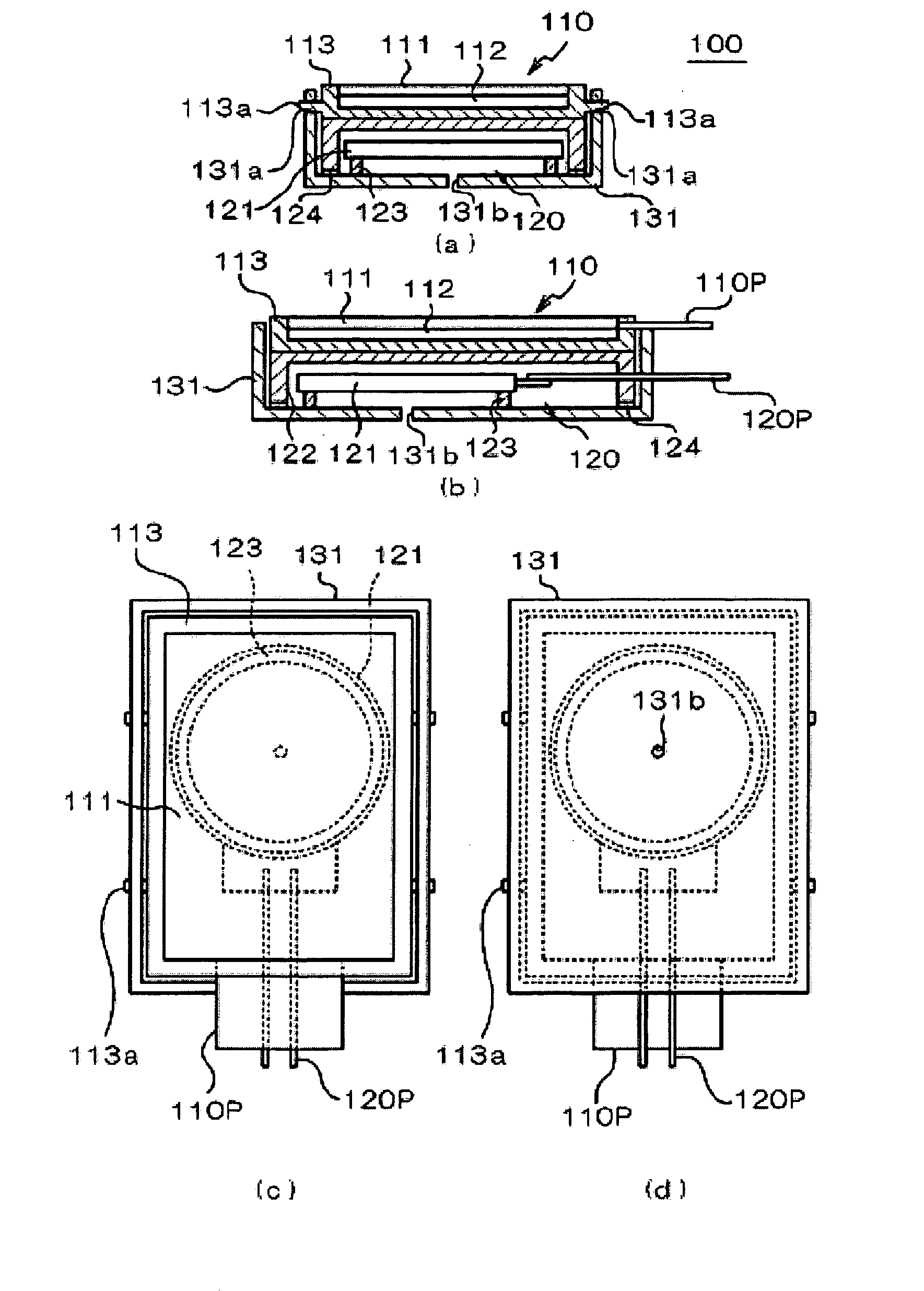
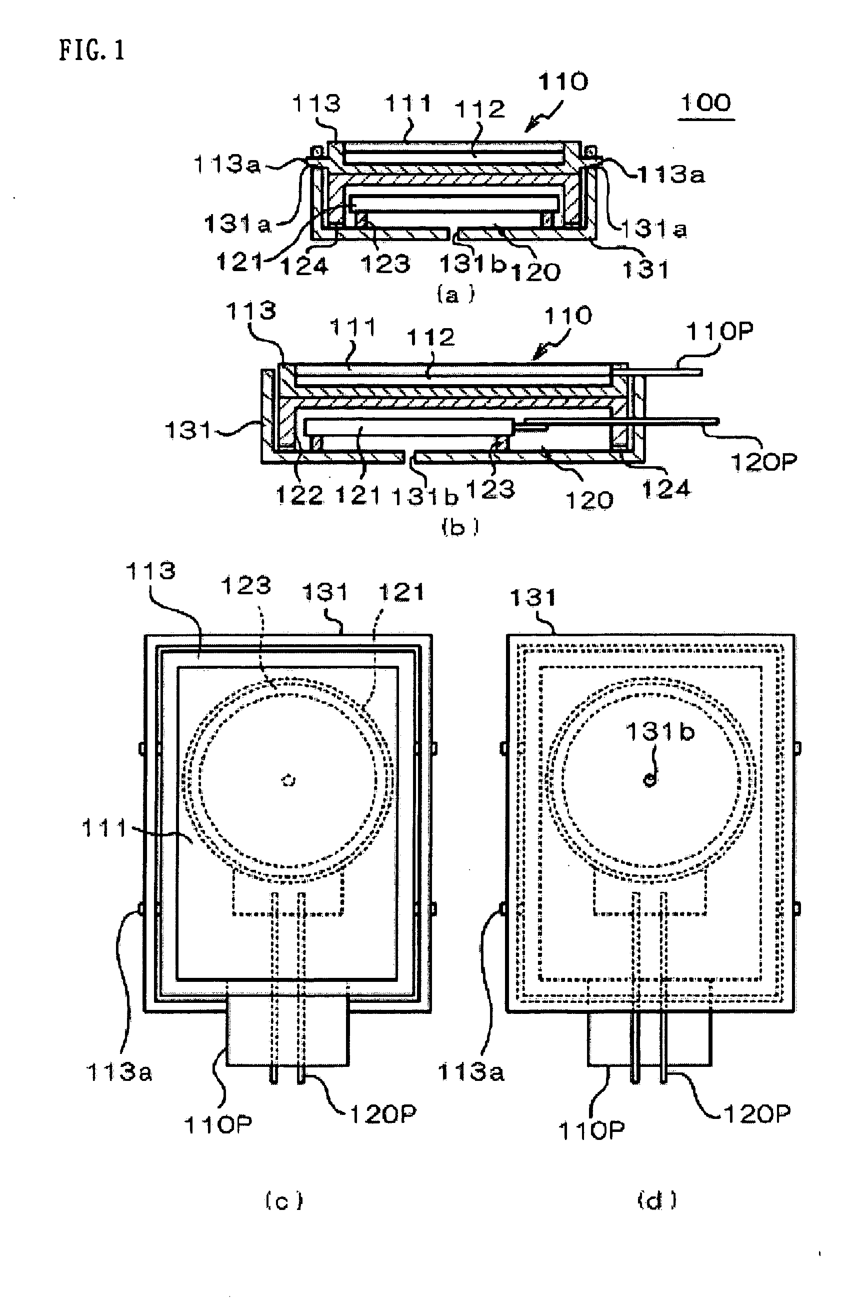
[0039]FIG. 1A shows a cross-sectional view showing a cross section taken along one direction (direction of the shorter side); FIG. 1B shows a cross-sectional view showing a cross section taken along the other direction (direction of the longer side); FIG. 1C shows a plan view; and FIG. 1D shows a bottom view of the electro-optical device with a sound generating body 100 according to the present invention. FIG. 4A is a side view of the electro-optical device with a sound generating body 100. The electro-optical device with a sound generating body 100 includes a display unit 110 provided with an electro-optical panel 111 and a sound generating unit 120 provided with a sound generating body 121.

[0040] The electro-optical panel 111 may be formed of various electro-optical devices such as a liquid crystal display panel, an organic electroluminescence panel, a plasma display panel, or a field emission panel. However, in this specification, it is basically assumed to be a liquid crystal d...

second embodiment

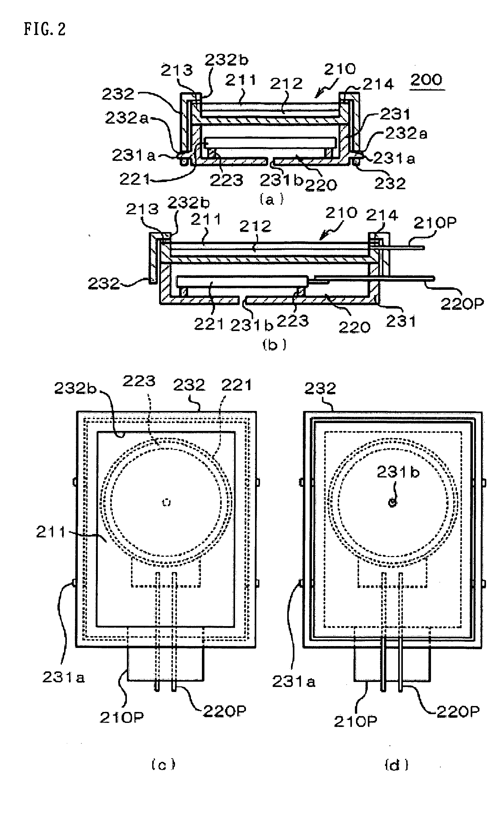
[0061] Referring now to FIGS. 2A to 2D, a second embodiment of the present invention will be described. FIG. 2A shows a cross-sectional view showing a cross section along one direction (direction of the shorter side) of an electro-optical device 200 with a sound generating body of the second embodiment; FIG. 2B shows a cross-sectional view showing a cross section along another direction (direction of the longer side); FIG. 2C shows a plan view; and FIG. 2D shows a bottom view. FIG. 4B is a side view of the electro-optical device 200 with a sound generating body.

[0062] The electro-optical device 200 with a sound generating body includes a display unit 210 provided with an electro-optical panel 211, and a sound generating unit 220 provided with a sound generating body 221. Since the electro-optical panel 211, a back light 212, a panel holding frame 213, the sound generating body 221, a supporting member 223, wiring members 210P, and 220P are the same as those in the first embodiment,...

third embodiment

[0066] Referring now to FIGS. 3A to 3D, a third embodiment of the present invention will be described. FIG. 3A shows a cross-sectional view showing a cross section taken along one direction (direction of the shorter side) of an electro-optical device 300 with a sound generating body of the third embodiment; FIG. 3B shows a cross-sectional view showing a cross section taken along another direction (direction of the longer side); FIG. 3C shows a plan view and FIG. 3D shows a bottom view. FIG. 4C is a side view of the electro-optical device 300 with a sound generating body.

[0067] In the electro-optical device 300 with a sound generating body according to this embodiment includes a display unit 310 provided with an electro-optical panel 311 and a sound generating unit 320 provided with a sound generating body 321. The electro-optical panel 311, a backlight 312, a panel holding frame 313, the sound generating body 321, a sound generating frame 322, a supporting member 323, a shock absor...


PUM


Abstract

An electro-optical device with a sound generating body is disclosed, in which an electro-optical device and a sound generating body can be mounted compactly and which can eliminate necessity of acoustic design of the sound generating body for an enclosure of an electronic apparatus for accommodating the electro-optical device. The electro-optical device of the present invention includes a first frame, a second frame opposed to the first frame, a third frame interposed between the first frame and the second frame, an electro-optical panel supported by the first frame, and a sound generating body supported by the second frame and covered by the second frame and the third frame, the sound generating body being arranged so as to be two-dimensionally overlapped the electro-optical panel.

Description

RELATED APPLICATIONS [0001] This application claims priority to Japanese Patent Application Nos. 2003-340322 filed Sep. 30, 2003, and 2004-237069 filed Aug. 17, 2004 which are hereby expressly incorporated by reference herein in their entirety. BACKGROUND [0002] 1. Field of the Invention [0003] The present invention relates to an electro-optical device and an electronic apparatus and, more specifically, to a structure of an electro-optical device with a sound generating body suitable for mounting on a mobile-type electronic apparatus. [0004] 2. Description of Related Art [0005] In general, an electro-optical device is mounted on various types of electronic apparatus as a display body, and in many cases, it is mounted within the electronic apparatus together with a sound generating body such as a speaker. Generally, in the electronic apparatus in the related art, the electro-optical device (for example, a liquid crystal display device) is stored in an enclosure in a state of being ap...

Claims


Application Information

Patent Timeline
IPC IPC(8): G02F1/1333G09F9/00H04B1/38H04M1/02H04R1/02H04R17/00H04R23/00H04R25/00
CPCH04R23/008H04B1/40
Inventor WADA, HIROSHIKAWAKAMI, HISANORIKOBAYASHI, AKIO
Owner BOE TECH GRP CO LTD
Why Eureka
Try Eureka