

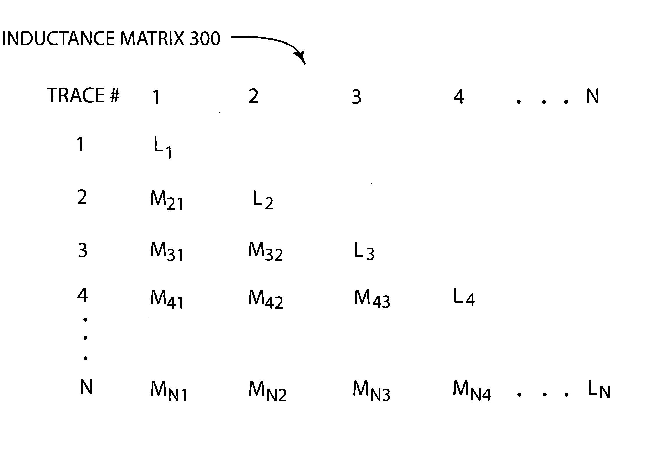
Cross talk analysis methodology and solution
a cross-talk analysis and cross-talk technology, applied in error detection/correction, program control, instruments, etc., can solve problems such as cross-talk, increase the frequency of operation, and increase the problem, so as to achieve the effect of modeling equivalent circuits
- Summary
- Abstract
- Description
- Claims
- Application Information
AI Technical Summary
Benefits of technology
Problems solved by technology
Method used
Image

Examples
Embodiment Construction
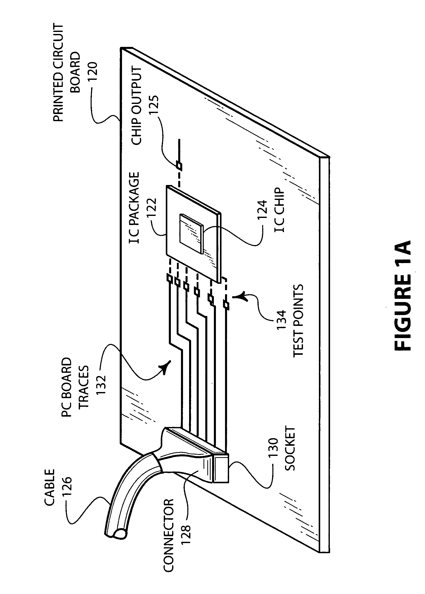
[0022]FIG. 1A is a schematic illustration of an integrated circuit high frequency transmission system. The system includes a cable 126 that is connected to a driver (not shown). The cable 126 is also coupled to a connector 128 that is inserted in a socket 130 on the printed circuit board 120. The socket 130 is connected to a series of printed circuit board traces 132. These printed circuit board traces 132 have accessible test points 134 for connecting an oscilloscope or other test device to check the signal waveforms. These test points 134 allow testing of the signal waveform prior to transmission to the integrated circuit package 122. Mounted on the integrated circuit package 122 is an integrated circuit chip 124 that receives the high frequency signals transmitted from the cable 126.
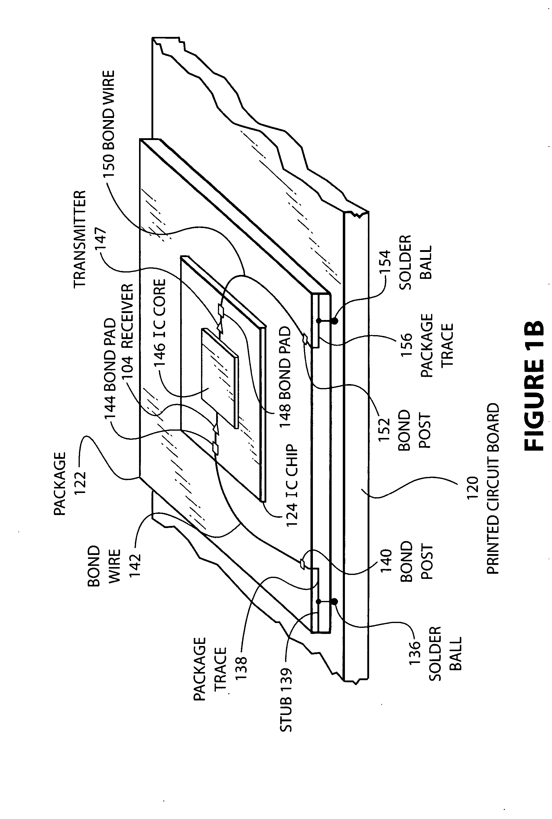
[0023] Frequently, cross talk can occur as a result of the routing of the PC board traces 132. More often, however, cross talk can occur from routing of traces in the IC package 122, bond wires that ...
PUM
 Abstract
Description
Claims
Application Information