Gas generating system and method for inerting aircraft fuel tanks

a fuel tank and gas generation system technology, applied in the field of gas generation systems, can solve the problems of displacement of approximately 3.5% of the volume of the tank, inefficiency associated with maintenance foam removal, art inerting system, etc., to prevent the entry of contaminants, prevent nitrogen flow, and prevent the effect of nitrogen flow

Active Publication Date: 2005-06-02
HONEYWELL INT INC
View PDF96 Cites 92 Cited by
  • Summary
  • Abstract
  • Description
  • Claims
  • Application Information

AI Technical Summary

Benefits of technology

[0008] Another aspect of the present invention includes a duct assembly with a bleed air inlet and a ram air inlet for ducting an air stream; an air stream exit; a control loop system having at least one control loop, which may include a conduit for nitrogen transfer from the ASM assembly and a pressure sensor for determining pressure in the conduit and generating at least one pressure value corresponding to the pressure; and a conduit exit for transferring nitrogen enriched air (NEA) from the ASM assembly; a controller monitor for receiving a pressure value and selectively preventing nitrogen flow; a primary heat exchanger for receiving the air stream from the ducting assembly and cooling the air stream, the primary heat exchanger located downstream from the at least one bleed air inlet and located downstream from the at least one ram air inlet; a gas generating system heat exchanger for receiving the air stream from the duct assembly, cooling the air stream, and providing the air stream to the duct assembly; an ejector for drawing in air over the gas generating heater exchanger and for ejecting a portion of the air stream, the ejector mechanically associated with duct assembly; a filter for filtering contaminates from the air stream, the filter mechanically associated with the duct assembly; a first temperature sensor and a second temperature sensor, each for determining temperature in the duct assembly and generating a temperature value corresponding to the temperature, each temperature sensor mechanically associated with the duct assembly; a controller monitor for receiving a temperature value and a pressure value, and generating a corresponding command signal; a panel indicator for visual confirmation of component status, the panel indicator electronically associated with the controller monitor; an altitude rate switch for monitoring changes in altitude and sending a signal corresponding to the change to the controller; a valve assembly for receiving and responding to the command signal, the valve assembly including at least one valve selected from a group essentially comprising a pressure regulating and shutoff valve, check valve, a flow shutoff valve, an ejector shutoff valve, a thermal shutoff valve, an ASM shutoff valve, and an isolation valve); an air separation module (ASM) assembly having a primary module and at least one secondary module, each module for receiving the air stream from the duct assembly; separating nitrogen enriched air (NEA) from the air stream; and providing nitrogen to the duct assembly, the ASM assembly located downstream from the at least one temperature sensor; at least one flow control orifice for controlling receiving and regulating nitrogen flow from the ASM assembly via the duct assembly, the at least one flow control orifice associated with a portion of the duct assembly located downstream from the ASM assembly; and at least one NEA check valve associated with the duct assembly, the check valve for preventing entry of contaminants into the duct assembly.
[0009] Still another aspect of the present invention includes a duct assembly for ducting an air stream, with at least one bleed air inlet, at least one ram air inlet, and at least one air stream exit, a control loop system with a primary control loop and a secondary control loop; at least one pressure sensor for determining pressure in the conduit and generating at least one pressure value corresponding to the pressure; at least one conduit exit for transferring nitrogen enriched air (NEA); a controller monitor for selectively preventing NEA flow; a primary heat exchanger for receiving the air stream from the ducting assembly and cooling the air stream, the primary heat exchanger located downstream from the at least one bleed air inlet and located downstream from the at least one ram air inlet; a gas generating system heat exchanger for receiving the air stream from the duct assembly, cooling the air stream, and providing the air stream to the duct assembly; a first temperature sensor and a second temperature sensor, each temperature sensor for determining temperature in the duct assembly and generating a temperature value corresponding to the temperature, the temperature sensors mechanically associated with the duct assembly; a controller monitor for receiving a temperature value and a pressure value, and generating a corresponding command signal; a valve assembly for receiving and responding to the command signal, the valve assembly including at least one of the following: a pressure regulating and shutoff valve, a check valve, a flow shutoff valve, an ejector shutoff valve, a thermal shutoff valve, an ASM shutoff valve, and an isolation valve; an air separation module (ASM) assembly having a primary module and at least one secondary module, each module for receiving the air stream from the duct assembly; separating nitrogen enriched air (NEA) from the air stream; and providing the NEA to the duct assembly, the ASM assembly located downstream from the at least one temperature sensor; a primary flow shutoff valve for controlling NEA flow, the primary flow shutoff valve located downstream from the primary ASM and a secondary flow shutoff valve for controlling NEA flow, the secondary flow shutoff valve located downstream from the at least one secondary ASM; a primary flow control orifice and a secondary control orifice for controlling receiving and regulating NEA flow from the primary ASM and the at least one ASM, respectively, via the duct assembly, the primary flow control orifice and the secondary control orifice associated with a portion of the duct assembly located downstream from the ASM assembly; and a primary NEA check valve and a secondary NEA check valve for preventing entry of contaminants into the duct assembly, the primary NEA check valve and the secondary NEA check valve associated with the duct assembly.
[0010] Yet another aspect of the invention includes steps of ducting the air stream via a duct assembly with at least one bleed air inlet, at least one ram air inlet, and at least one air stream exit; receiving the air stream from the ducting assembly and cooling the air stream with a primary heat exchanger, the primary heat exchanger located downstream from the at least one bleed air inlet and located downstream from the at least one ram air inlet; receiving the air stream from the duct assembly with a gas generating system heat exchanger, cooling the air stream, and providing the air stream to the duct assembly; determining temperature in the duct assembly and generating a temperature value corresponding to the temperature via a first temperature sensor and a second temperature, each temperature sensor mechanically associated with the duct assembly; receiving a temperature value and a pressure value, and generating a corresponding command signal via a controller monitor; receiving and responding to the command signal via at least one valve, the at least one valve selected from a group essentially comprising a pressure regulating and shutoff valve, a check valve, a flow shutoff valve, an ejector shutoff valve, a thermal shutoff valve, an ASM shutoff valve, and an isolation valve; receiving the air stream from the duct assembly, separating nitrogen enriched air (NEA) from the air stream, and providing the NEA to the duct assembly via an air separation module (ASM) assembly having a primary module and at least one secondary module, the ASM assembly located downstream from both temperature sensors; controlling NEA flow through the duct assembly from the ASM assembly to the conduit exit via the at least one flow control orifice, the at least one flow control orifice associated with a portion of the duct assembly located downstream from the ASM assembly; and preventing the entry of contaminants into the duct assembly from the conduit exit.
[0011] A further aspect of the present invention includes steps of ducting an air stream through a duct assembly with at least one bleed air inlet, at least one ram air inlet, at least one air stream exit, and a conduit exit; receiving the air stream from the duct assembly and cooling the air stream with a primary heat exchanger located downstream from the at least one bleed air inlet and located downstream from the at least one ram air inlet; receiving the air stream from the duct assembly, cooling the air stream, and providing the air stream to the duct assembly with a gas generating system heat exchanger; drawing air into a duct assembly and over the gas generating system heat exchanger via an ejector mechanically associated with duct assembly; filtering contaminates from the air stream via a filter, the filter mechanically associated with the duct assembly; determining temperature in the duct assembly and generating a temperature value corresponding to each determined temperature via a first temperature sensor and a second temperature sensor, the temperature sensors mechanically associated with the duct assembly; receiving a temperature value and a pressure value, and generating a corresponding command signal via a controller monitor; visually confirming component status via a panel indicator, the panel indicator electronically associated with the controller monitor; monitoring changes in altitude and sending a signal corresponding to the change to the controller via an altitude monitor; receiving and responding to the command signal via at least one valve, the at least one valve selected from a group essentially comprising a pressure regulating and shutoff valve, a check valve, at least one flow shutoff valve, an ejector shutoff valve, a thermal shutoff valve, an ASM shutoff valve, and an isolation valve; receiving the air stream from the duct assembly; separating nitrogen enriched air (NEA) from the air stream; and providing the NEA to the duct assembly via an air separation module (ASM) assembly having a primary module and at least one secondary ASM module, the ASM assembly located downstream from the at least one temperature sensor; controlling, receiving, and regulating NEA flow from the ASM assembly via the duct assembly and via at least one flow control orifice, the at least one flow control orifice associated with a portion of the duct assembly located downstream from the ASM assembly; and preventing entry of contaminants into the duct assembly via at least one NEA check valve associated with the duct assembly.
[0012] A still further aspect of the present invention includes steps of receiving in and venting the air stream via at least one orifice of a duct assembly, (the at least one orifice may include at least one bleed air inlet; at least one ram air inlet; at least one ram exit; and at least one ram air overboard exit); determining pressure in the duct assembly and generating a pressure value corresponding to the pressure via at least one pressure sensor; determining temperature in two points in the duct assembly and generating a temperature value corresponding to the determined temperature via a first temperature sensor and a second temperature sensor; receiving the pressure value and the temperature values, and generating at least one command based on the received values via a controller monitor, the at least one command generated to selectively control flow to portions of the duct assembly via a controller monitor; receiving the air stream from the ducting assembly and cooling the air stream via a primary heat exchanger, the primary heat exchanger located downstream from the at least one bleed air inlet and located downstream from the at least one ram air inlet; receiving the air stream from the duct assembly, cooling the air stream, and providing the air stream to the duct assembly via a gas generating system heat exchanger; receiving and responding to the command signal via at least one valve, the at least one valve selected from a group essentially comprising a pressure regulating and shutoff valve, a check valve, a flow shutoff valve, an ejector shutoff valve, a thermal shutoff valve, an ASM shutoff valve, and an isolation valve; receiving the air stream from the duct assembly; separating nitrogen enriched air (NEA) from the air stream; and providing the NEA to the duct assembly via an air separation module (ASM) assembly having a primary module and at least one secondary module, the ASM assembly located downstream from the temperature sensors; controlling NEA flow from the ASM assembly via a primary flow shutoff valve located downstream from the primary ASM and a secondary flow shutoff valve, the secondary flow shutoff valve located downstream from the at least one secondary ASM; receiving and regulating NEA flow from the primary module via a primary flow control orifice and receiving and regulating NEA flow from the at least one secondary module, the primary flow control orifice and the secondary control orifice associated with a portion of the duct assembly located downstream from the ASM assembly; and preventing entry of contaminants into the duct assembly via a primary NEA check valve located downstream from the primary flow control orifice and a secondary NEA check valve located downstream from the secondary flow control orifice; and transferring the NEA from the duct assembly via at least one conduit exit.

Problems solved by technology

Drawbacks exist, however, in foam inerting systems, including displacement of approximately 3.5% of the volume of the tank and inefficiencies associated with mandatory removal of the foam for maintenance purposes.
The prior art inerting systems, however, have drawbacks, including a requirement for costly operational components.
The components monopolize a predominance of the space and weight allowances for an aircraft, impeding overall system design.
Further, redundant processes such as repetitive airflows into and from air conditioner components result in operational inefficiencies, again increasing the overall costs of such systems.

Method used


Image

  • Gas generating system and method for inerting aircraft fuel tanks
  • Gas generating system and method for inerting aircraft fuel tanks
  • Gas generating system and method for inerting aircraft fuel tanks

Examples


Embodiment Construction

[0019] The following detailed description is of the best currently contemplated modes of carrying out the invention. The description is not to be taken in a limiting sense, but is made merely for the purpose of illustrating the general principles of the invention, since the scope of the invention is best defined by the appended claims.

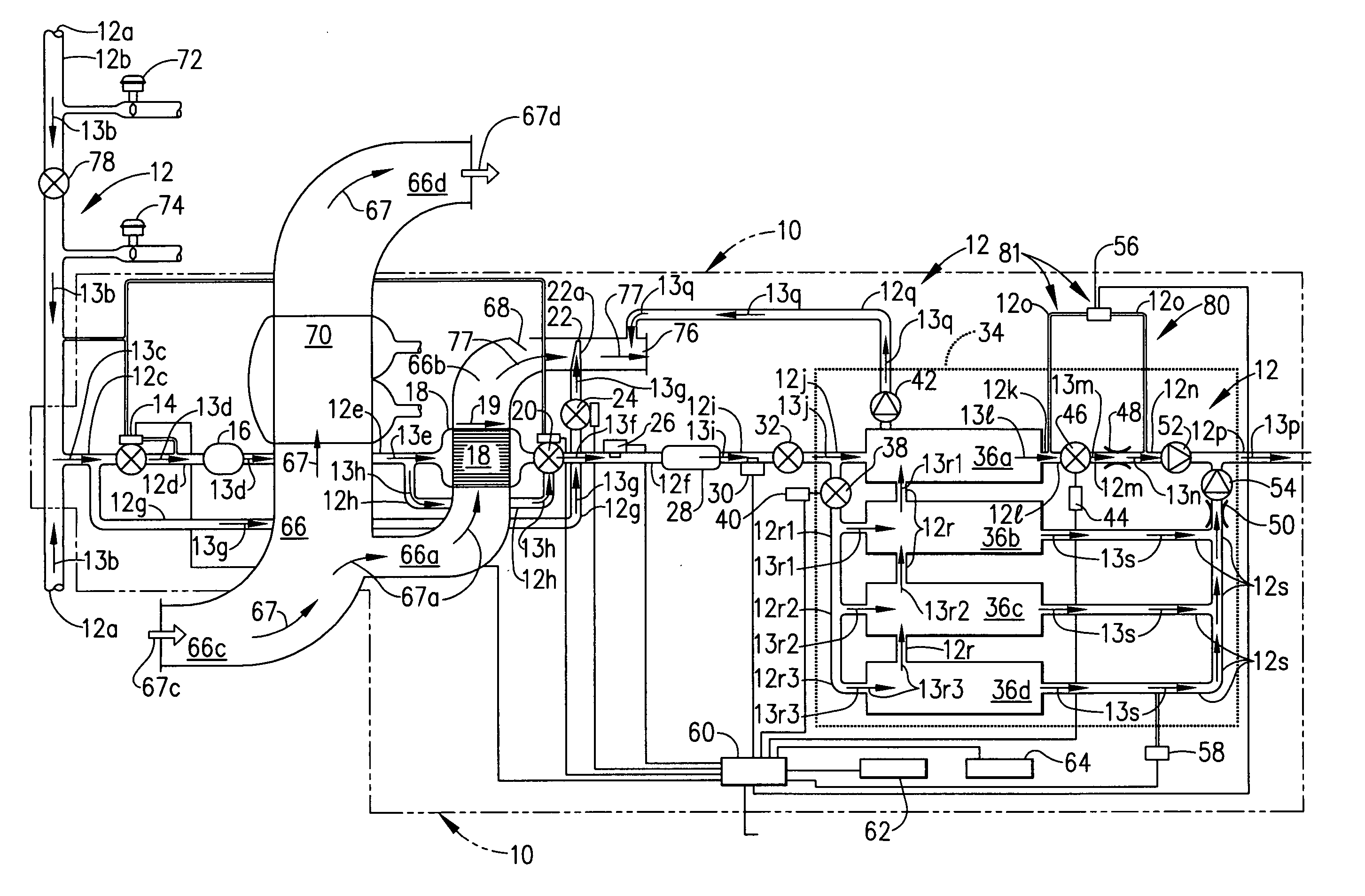
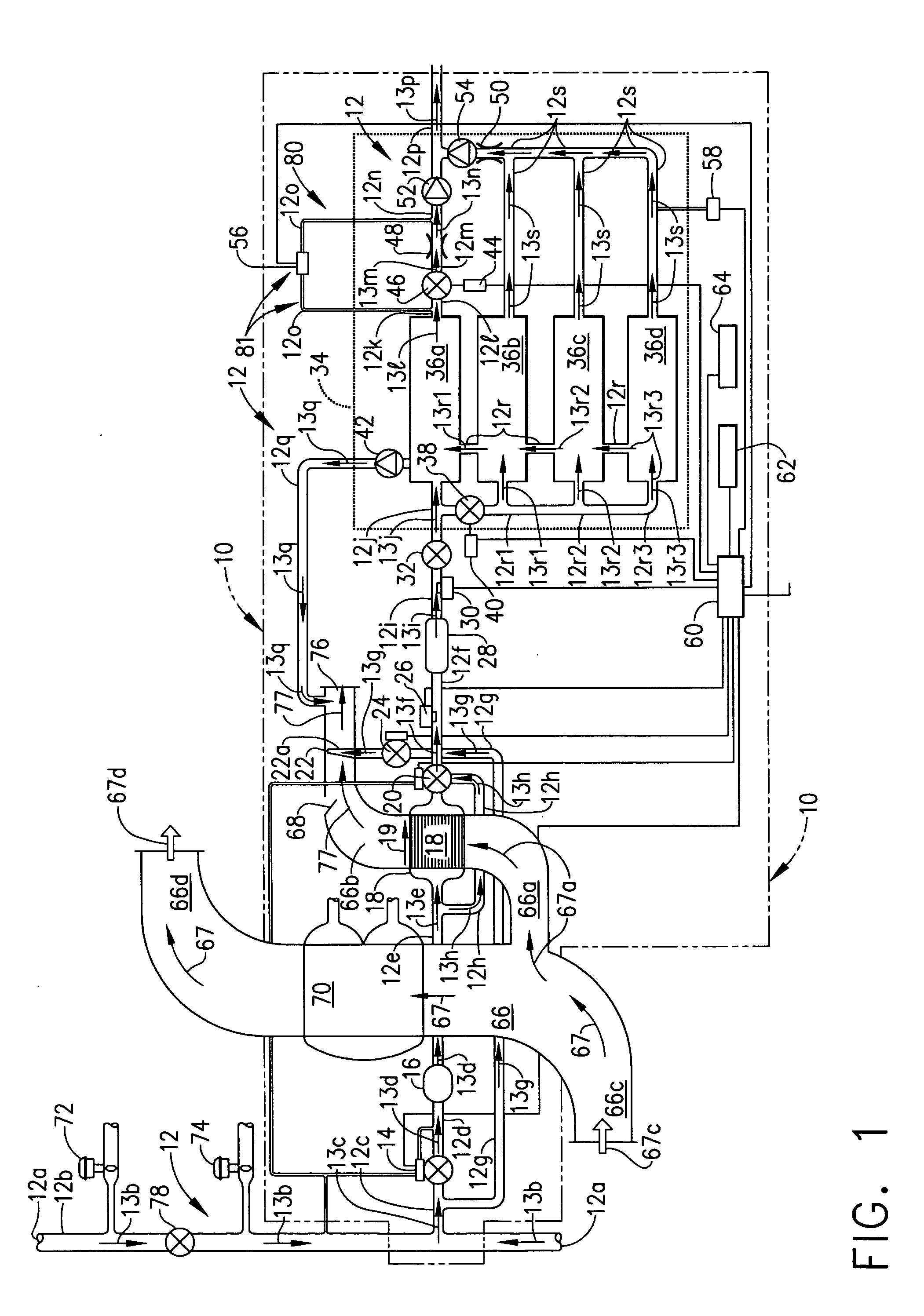
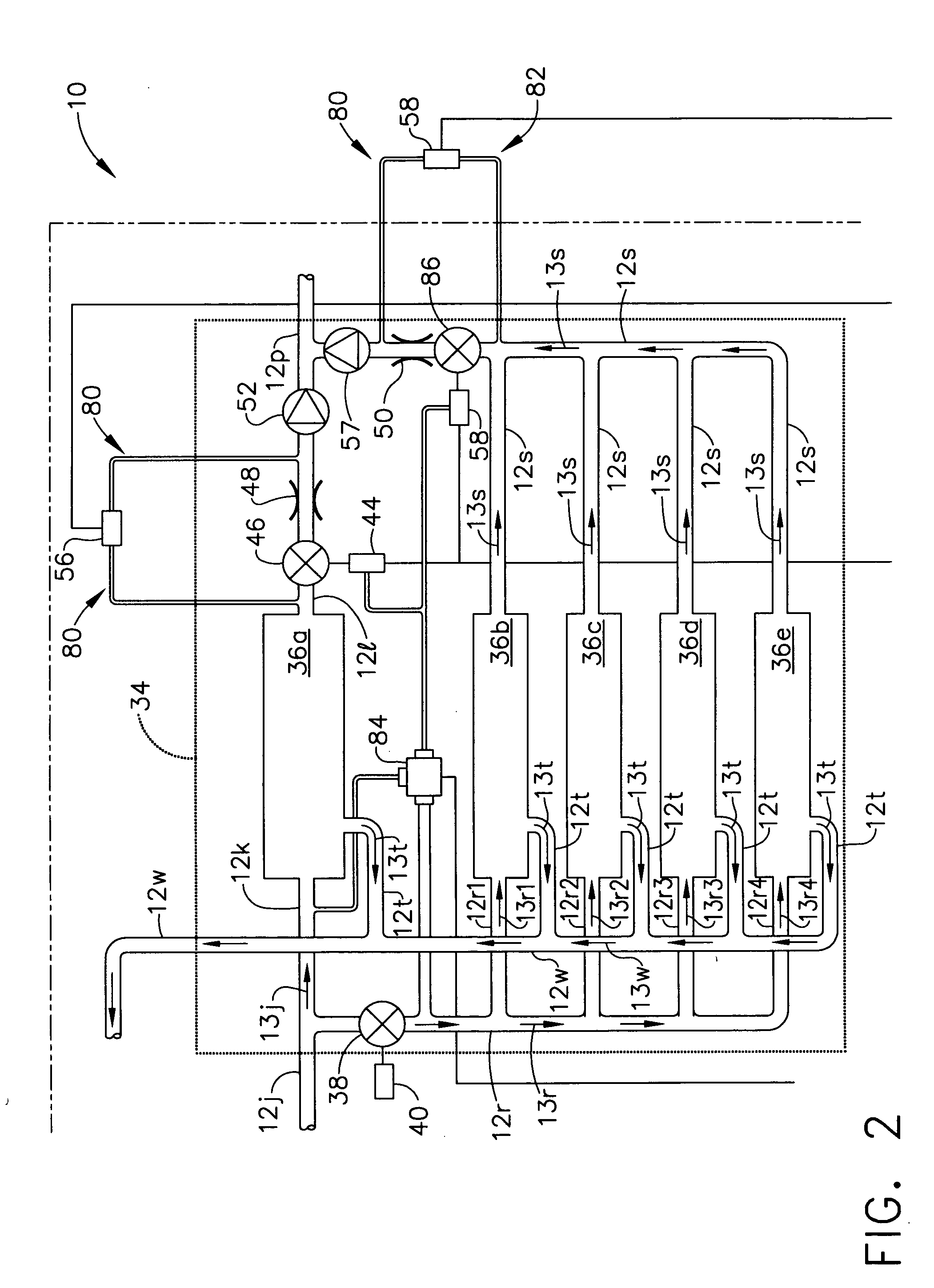
[0020] Broadly, the present invention provides a system and method for generating a gas from an air stream; for example, isolating nitrogen from an air mixture and providing the isolated nitrogen for use as an inerting agent. Unlike inventions of the prior art, which require a host of specific components and costly, redundant subprocesses, the present invention may utilize a minimal and flexible set of components as well as streamlined subprocesses, resulting in a cost-effective system and method.

[0021] More specifically, the present invention recovers nitrogen from an air stream, using the recovered nitrogen for inerting systems or other application...


PUM

PropertyMeasurementUnit
temperatureaaaaaaaaaa

Abstract

The present invention provides a system and method for generation of nitrogen enriched air for inerting aircraft fuels tanks. One embodiment of the present invention includes a duct assembly; a primary heat exchanger; a gas generating system heat exchanger; a first temperature sensor; a second temperature sensor; a controller monitor; a valve; an air separation module assembly having a primary module and a secondary module; at least one flow control orifice; and a pressure sensor. The present invention utilizes a minimal complement of components and streamlined processes, thus minimizing structural and operational costs while optimizing performance and safety features.

Description

BACKGROUND OF THE INVENTION [0001] The present invention generally relates to gas generation systems and particularly to systems and methods for nitrogen generation and for inerting aircraft fuel tanks. [0002] Aircraft fuel tanks contain potentially combustible combinations of oxygen, fuel vapors, and ignition sources. The flash point for explosion varies according to temperature, pressure and fuel type. Industry literature suggests that a “limiting oxygen content” (LOC) immunizes a fuel tank from explosion, regardless of flash point factors. Industry standards suggest various limits for the LOC. For example, current standards suggest that the minimum amount of oxygen needed to sustain combustion at sea level is slightly less than 12%. That amount increases to 14.5% at 30,000 feet above sea level, Croft, John, “FAA ‘Breakthrough’: Onboard Inerting”, Aviation Week &Space Technology, Jan. 6, 2003. [0003] Attempts have been made to reduce the oxygen level in aircraft fuel tanks by prov...

Claims


Application Information

Patent Timeline
Patent Type & Authority Applications(United States)
IPC IPC(8): B01D53/02B01D53/04B01D53/047B64D37/32
CPCB01D53/0454B01D53/047B01D2256/10B01D2257/102B01D53/0438B01D2259/404B01D2259/4575B64D37/32B64D2013/0677B01D2259/40009
Inventor LEIGH, JAMES E.FELLAGUE, KADER A.ISELLA, GIORGIO C.ROACH, PAUL J.
Owner HONEYWELL INT INC
Why Eureka
Try Eureka