
Static dissipative fuel dispensing nozzle

a technology of static discharge and dispensing nozzle, which is applied in the direction of liquid transfer device, liquid handling, packaging goods type, etc., can solve the problems of causing danger, customers being injured, and dispensing volatile fuel to present fire hazards, and achieve the effect of reducing static discharg

Inactive Publication Date: 2005-06-02
WAYNE FUELING SYST
View PDF24 Cites 7 Cited by
  • Summary
  • Abstract
  • Description
  • Claims
  • Application Information

AI Technical Summary

Benefits of technology

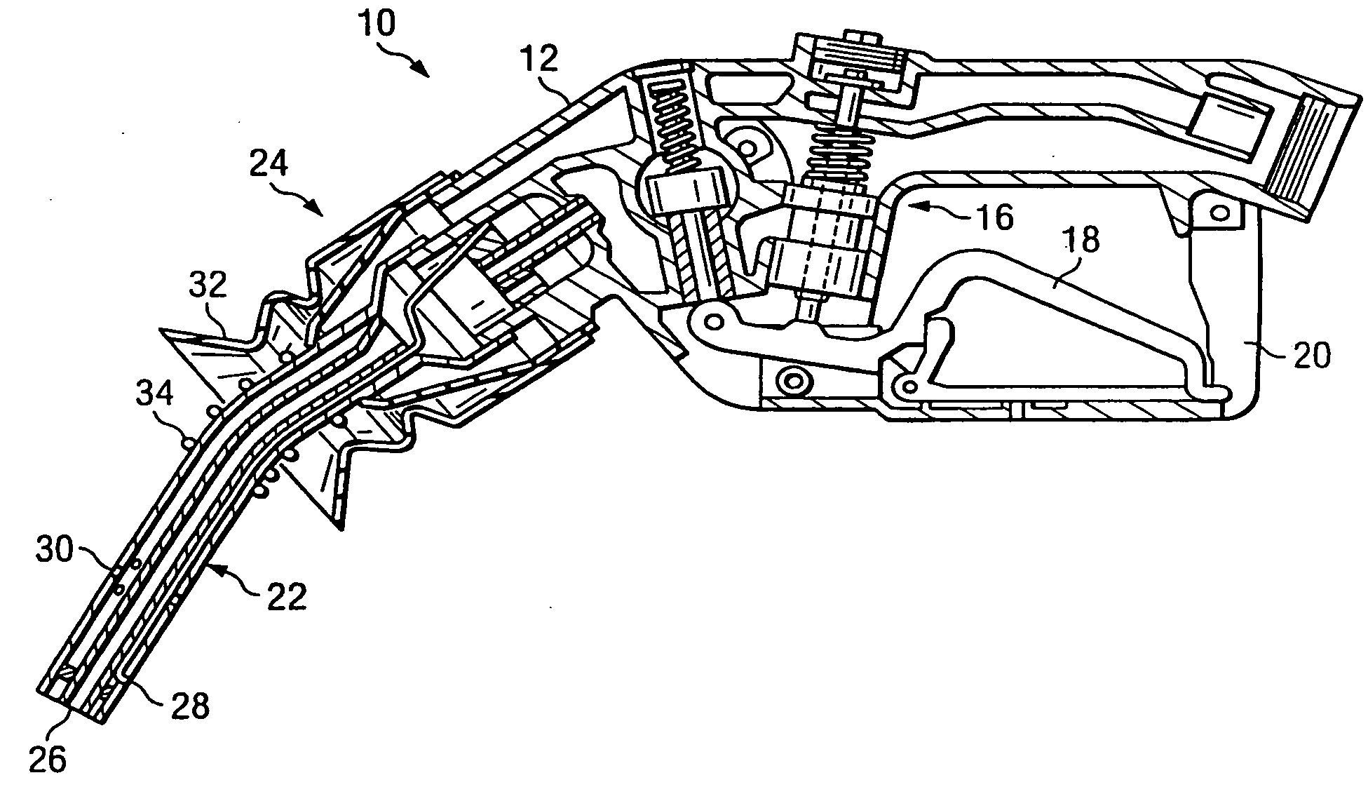
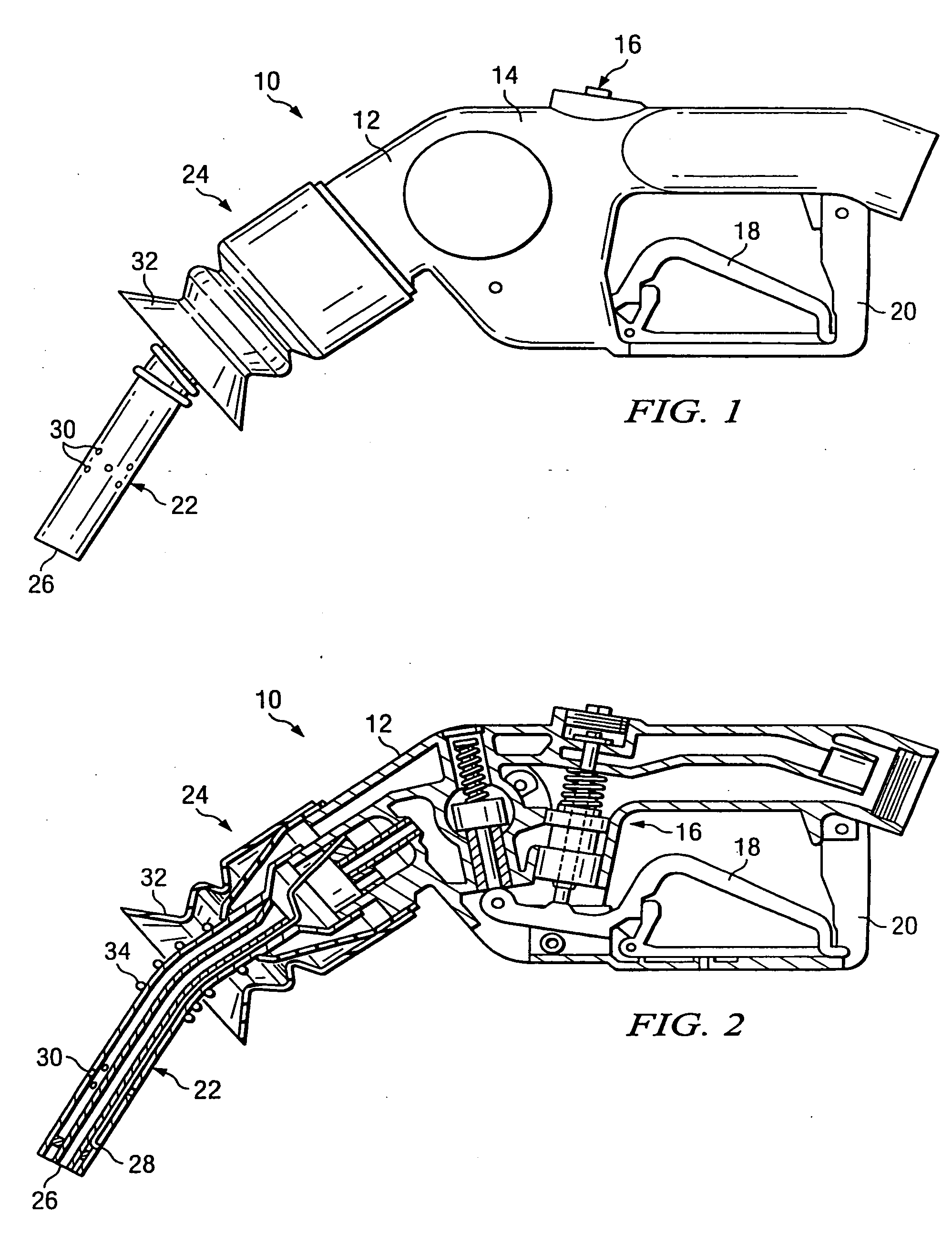
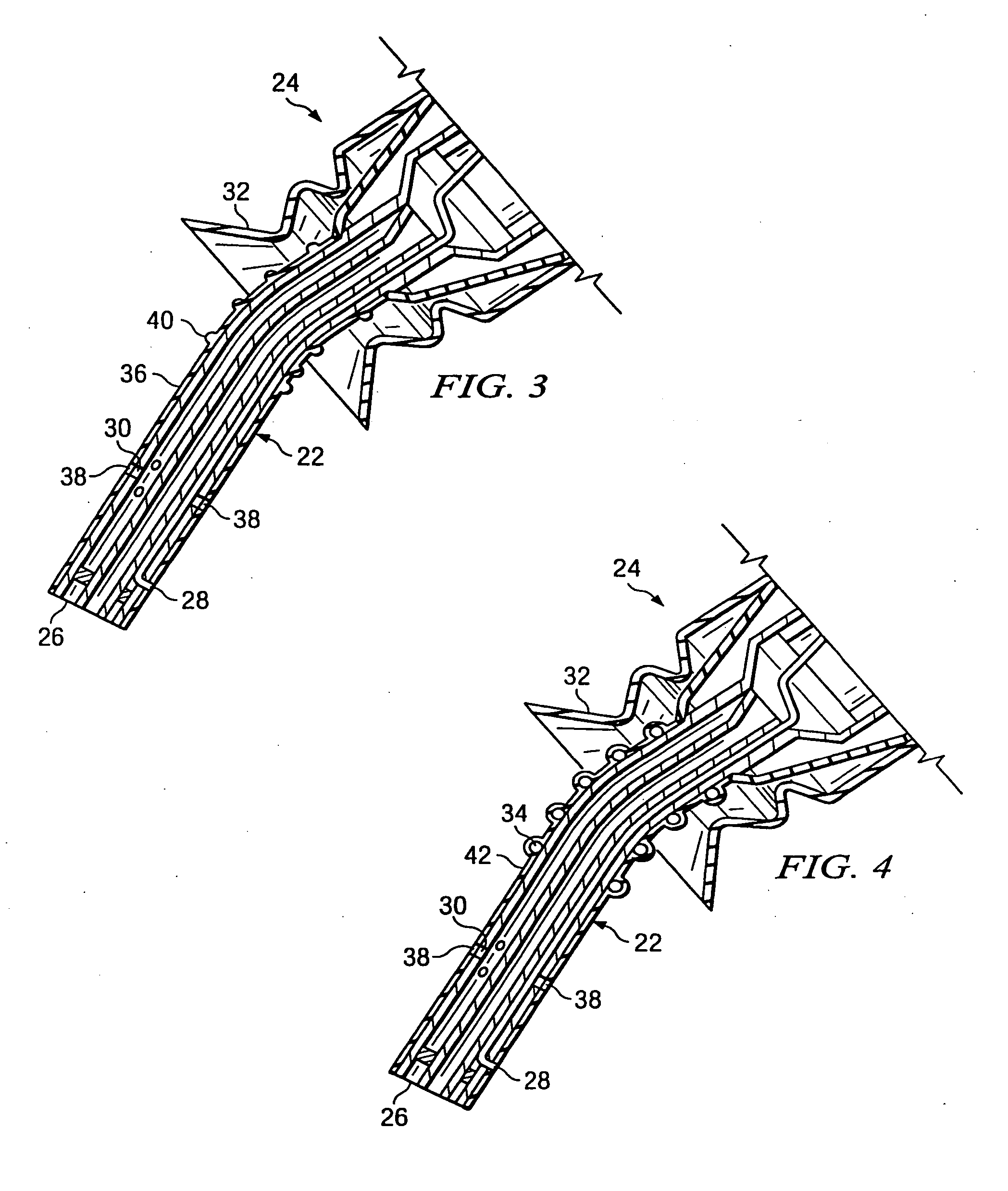
[0011] An exemplary fuel dispensing nozzle includes a body, a handle connected to the body, a handle guard connected to the body and generally surrounding the handle, and a spout extending from the body. Parts of the nozzle are made of, or covered in, static dissipative materials. Additionally, an exemplary method for reducing static discharge in existing nozzle installations includes the application of static dissipative material to existing nozzles to address certain static discharge risks.

Problems solved by technology

It is understood in the industry that dispensing volatile fuel may present a fire hazard if an ignition source is present near the dispensing nozzle.
The danger is created by the fuel vapor emanating from the nozzle container interface.
Unfortunately, customers are injured from fires started by static discharge in the area immediately surrounding the nozzle.
Then, as the nozzle is withdrawn from the can, the metallic highly electrically conductive nozzle spout may pass in close enough proximity to a statically-charged portion of the can to cause a static discharge between the can and the spout, which under the right conditions, can ignite the vapor in the immediate area causing a fire which can damage property and cause personal injury.
The act of sliding in and out of a vehicle, or walking across a carpeted floor, can cause static electricity to build up in the customer's body.
In such a situation, flammable vapor or fumes may have built up in the area of the nozzle such that a fire or explosion may be ignited that is capable of causing damage to property and personal injury.
Unfortunately, these grounding straps do not address the build-up of static electricity in the customer's body as they are moving across the seat of their vehicle or walking on the carpet in the convenience store, nor do they address the build-up of static discharge in a gasoline can that is placed on an insulative surface, such as a bed liner of a pickup truck.
To the extent users do not follow the directions clearly labeled on the dispenser, the above methods do not effectively reduce the static discharge occurrence in and around the nozzle area.

Method used


Image

  • Static dissipative fuel dispensing nozzle
  • Static dissipative fuel dispensing nozzle
  • Static dissipative fuel dispensing nozzle

Examples


Embodiment Construction

[0021] Definitions

[0022] As used herein, “static discharge” means the release of static electricity via an arc or spark between a charged object and another object. Static discharge can happen when a body comes into contact with another body at a sufficiently different potential. Electrostatic discharge can range from a voltage level just high enough to create a spark up to between 30,000-40,000 volts or higher. The actual voltage needed to create a spark depends on environmental factors, such as temperature and humidity, as well as material properties. Typically, static charge is the result of a transfer of electrons that occurs due to the sliding, rubbing or separating of a material which is a prime generator of electrostatic voltages, such as plastics, fiberglass, rubber, textiles, etc.

[0023] As used herein, the term “static dissipative material” means materials which have a surface resistivity of between approximately 0.5 megaohms / square (0.5×10⁶ Ohm / sq) and approximately 1,00...


PUM

PropertyMeasurementUnit
voltageaaaaaaaaaa
surface resistivityaaaaaaaaaa

Abstract

A fuel dispensing nozzle includes a body, a handle connected to the body, a handle guard connected to the body and generally surrounding the handle, and a spout extending from the body. Parts of the nozzle are made of, or covered in, static dissipative materials. Additionally, a method for reducing static discharge in existing nozzle installations includes the application of static dissipative material to existing nozzles to address certain static discharge risks.

Description

[0001] This application is a continuation-in-part of application Ser. No. 10 / 417,679, filed Apr. 17, 2003, the disclosure of which is incorporated by reference herein. BACKGROUND OF THE INVENTION [0002] 1. Technical Field of the Invention [0003] The invention relates generally to safety devices in a combustible environment and more particularly to static discharge reduction between a nozzle and a static-electrical charged object. [0004] 2. Description of Related Art [0005] Fuel dispensing nozzles are well-known in the art for dispensing fuel from a fuel supply into a container. A typical example would be the fuel dispensing nozzle at a retail gasoline station wherein the dispensing nozzle is at the end of a hose connected to a dispenser which is connected to an underground storage tank. The nozzle will typically contain a valve that is actuated by the customer to dispense fuel from the underground storage tank through the dispenser, through the hose, through the nozzle and into the ...

Claims


Application Information

Patent Timeline
Patent Type & Authority Applications(United States)
IPC IPC(8): B67D7/32B67D7/42
CPCB67D7/42B67D7/3236
Inventor DAVIS, E. LINWOOD
Owner WAYNE FUELING SYST
Learn More