
Method and apparatus for cutting adhesive tape

a technology of adhesive tape and cutting tool, which is applied in the field of cutting tool and cutting tool, can solve the problems of increasing the thickness of the adhesive tape in the portion, difficult for the needle-shaped cutter, and difficult to accurately cut the adhesive tape in the circular shape, etc., and achieves the effect of facilitating cutter angle adjustment and good precision

Inactive Publication Date: 2005-06-02
NITTO DENKO CORP
View PDF10 Cites 7 Cited by
  • Summary
  • Abstract
  • Description
  • Claims
  • Application Information

AI Technical Summary

Benefits of technology

The present invention provides an adhesive tape cutting method and apparatus that can cut an adhesive tape accurately without leaving any whisker-shaped residue. This is achieved by making the cutter revolve along a circular path while keeping the cutter tilted towards the inner circumference side in the revolution. The cutter comes into contact with the adhesive tape and the surface of a ring frame on which a semiconductor wafer is mounted, resulting in a smooth cutting process. The apparatus includes a rotating mechanism, an angle adjusting mechanism, and a lifting mechanism, which can support the cutter and cut the adhesive tape accurately. The method and apparatus can be used in the semiconductor industry for integrating a semiconductor wafer with a ring frame.

Problems solved by technology

When remained adhesive tapes are stacked, the thickness of the adhesive tapes increases in the portion and it may cause a problem in following processes such as a process of separating the protective tape from the surface of the wafer and a wafer process such as a dicing process.
Consequently, it is difficult for the needle-shaped cutter as described in JP-A 11-3876 (1999) to cut the adhesive tape so that the cutting start point and the cutting end point meet are made coincide with each other.
It becomes difficult to accurately cut the adhesive tape in a circular shape and, in some cases, the adhesive tape remains in a whisker shape at the cutting start point and the cutting end point.

Method used


Image

  • Method and apparatus for cutting adhesive tape
  • Method and apparatus for cutting adhesive tape
  • Method and apparatus for cutting adhesive tape

Examples


Embodiment Construction

[0033] An embodiment of the present invention will be described below with reference to the drawings.

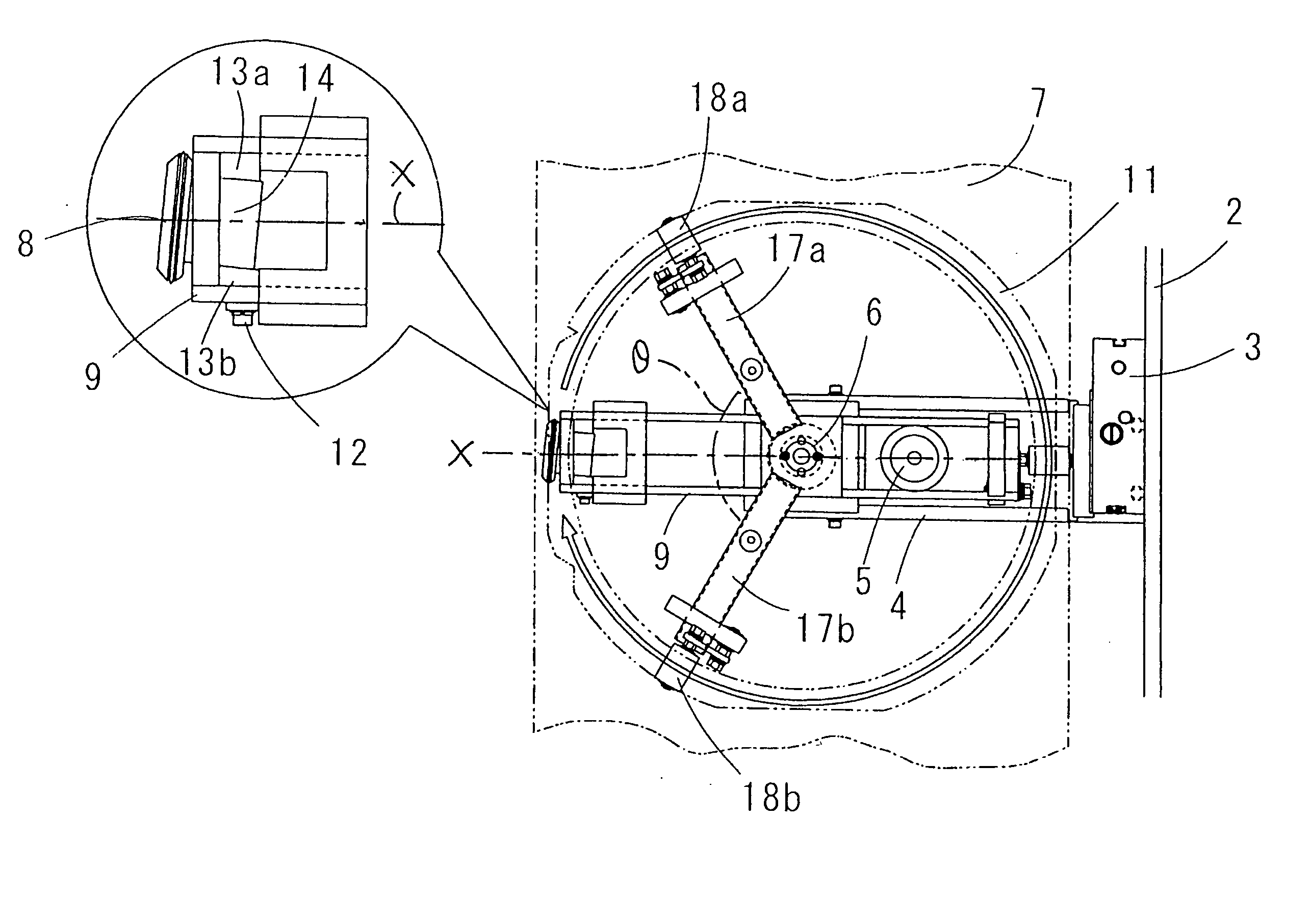
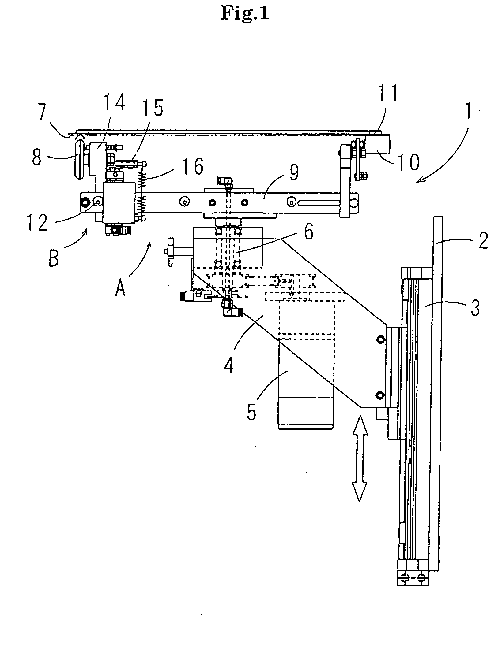
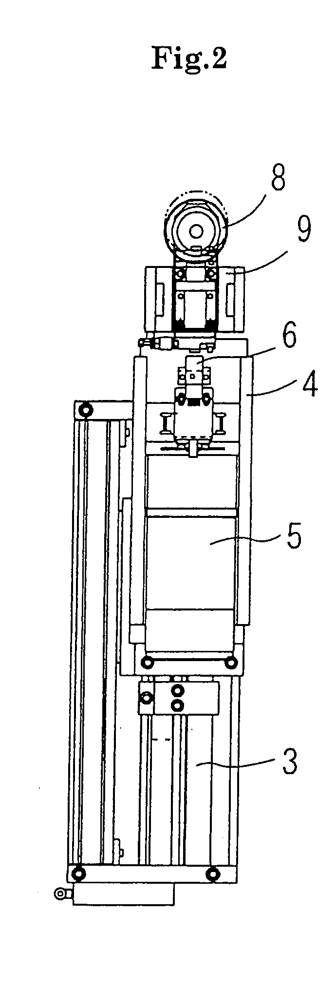
[0034]FIGS. 1, 2 and 3 are a schematic side view, a schematic front view and a schematic plan view, respectively, of an adhesive tape cutting apparatus according to the present invention. In the following description of the embodiment, a method of cutting an adhesive tape joined to a ring frame on which a wafer is mounted will be described as an example. However, the present invention is not limited to the following embodiment.

[0035] An adhesive tape cutting apparatus 1 according to the embodiment comprises, as shown in the schematic side view of FIG. 1, a frame 2 of an adhesive tape adhering apparatus or the like on which the apparatus 1 is provided, a guide 3 fixed to the frame 2, and a lifting frame 4 as a component of a lifting mechanism supported to the guide 3 so as to be movable in a vertical direction. The lifting frame 4 includes a rotating mechanism A for revolving a cutt...


PUM

PropertyMeasurementUnit
angleaaaaaaaaaa
revolving speedaaaaaaaaaa
open angleaaaaaaaaaa

Abstract

In a method of making a cutter revolve along a circumference of a circle having an optional size to cut an adhesive tape into a circular shape of a predetermined size, the cutter is made revolve while being tilted to an inner circumferential side in the revolving direction of the circumference, and a cutting start point and a cutting end point in a cutting path of the cutter are made coincide with each other.

Description

BACKGROUND OF THE INVENTION [0001] (1) Field of the Invention [0002] The present invention relates to a method and an apparatus for cutting an adhesive tape into a circular shape. More particularly, the present invention relates to a method and an apparatus for cutting an adhesive tape joined to a ring frame which is mounted at the time of dicing a semiconductor wafer. [0003] (2) Description of the Related Art [0004] Generally, a surface protective tape is preliminarily joined to the surface of a semiconductor wafer (hereinafter, simply referred to as a wafer), which has been subjected to a pattern forming process, and part of the surface protective tape, which protrudes from the outer circumference of the wafer is cut out along the outer peripheral edge of the wafer. In a state where the whole surface of the wafer is protected with the surface protective tape, a wafer back-side polishing process is performed on the back side of the wafer which is put upside down. After that, an adh...

Claims


Application Information

Patent Timeline
Patent Type & Authority Applications(United States)
IPC IPC(8): B26F1/38B65H35/06H01L21/301B65H35/08H01L21/00
CPCB26F1/3846Y10T156/108Y10T156/1348H01L21/67132Y10T83/8789Y10T83/7788B65H35/06B65H35/08
Inventor YAMAMOTO, MASAYUKI
Owner NITTO DENKO CORP
Learn More