Illumination assembly

a technology of illumination assembly and leds, which is applied in the direction of semiconductor devices for light sources, light and heating apparatus, printed circuit non-printed electric components association, etc., can solve the problems of reduced led life, limited device performance, and low density of leds within, and achieve improved thermal properties

Inactive Publication Date: 2005-06-02
3M INNOVATIVE PROPERTIES CO
View PDF98 Cites 200 Cited by
  • Summary
  • Abstract
  • Description
  • Claims
  • Application Information

AI Technical Summary

Benefits of technology

[0011] The present invention provides an illumination assembly having improved thermal properties. The assembly includes a substrate having an electrically insulative layer on a first side of the substrate and an electrically conductive layer on a second side of the substrate. A plurality of LEDs are d

Problems solved by technology

However, tightly packing large numbers of LEDs in an array is a long-term reliability concern since local heating, even with a globally efficient thermal conduction mechanism, can reduce the lifespan of the LEDs.
As a consequence, performance of the device is limited.
Although the more recent approaches improve the thermal properties of LED arrays, there are several disadvantages to these approaches.
Specifically, the substrates, whether they are inorganic material such as ceramic or organic material such as FR4 epoxy, have limited thermal conductivity and the thermal resistance from the heat generating LED to the heat dissipating part of the assembly limits the maximu

Method used


Image

  • Illumination assembly
  • Illumination assembly
  • Illumination assembly

Examples


Embodiment Construction

[0026] In the following detailed description of the preferred embodiments, reference is made to the accompanying drawings, which form a part hereof, and in which is shown by way of illustration specific embodiments in which the invention may be practiced. It is to be understood that other embodiments may be utilized and structural or logical changes may be made without departing from the scope of the present invention. The following detailed description, therefore, is not to be taken in a limiting sense, and the scope of the present invention is defined by the appended claims.

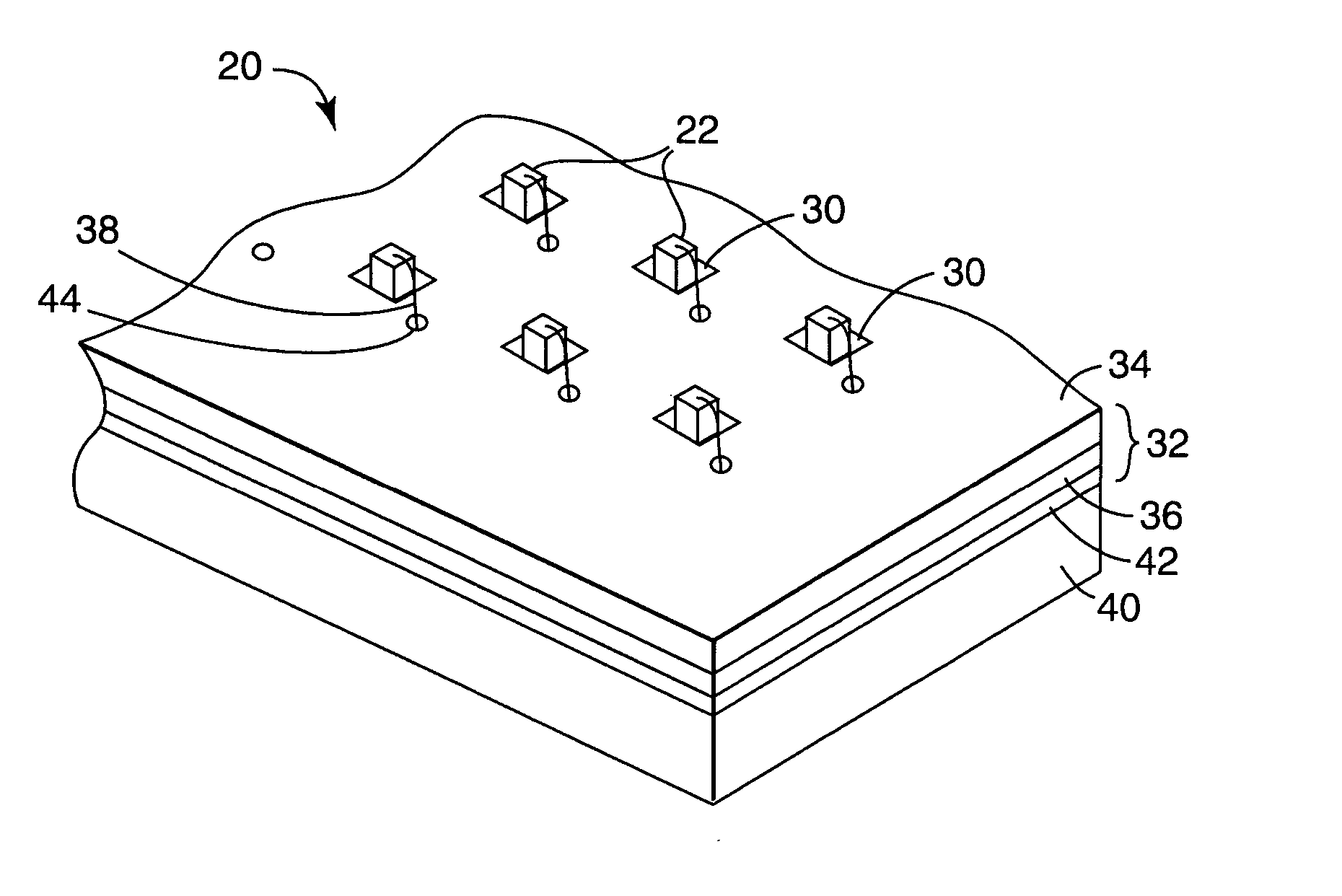
[0027] As used herein, LED dies include, but are not limited to, light emitting elements such as light emitting diodes (LEDs), laser diodes, and super-radiators, to name a few. LED dies are understood generally as optically emitting semiconductor bodies with contact areas for providing power to the diode.

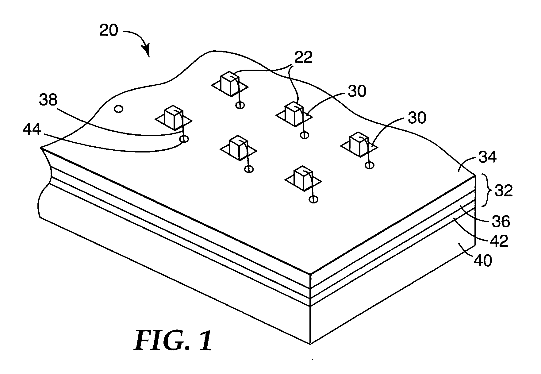
[0028]FIG. 1 shows a perspective view of one embodiment of a portion of an illumination assembly 20 accord...


PUM


Abstract

An illumination assembly includes a substrate having an electrically insulative layer on a first side of the substrate and an electrically conductive layer on a second side of the substrate. A plurality of LED dies is disposed on the substrate. Each LED die is disposed in a via extending through the electrically insulative layer on the first side of the substrate to the electrically conductive layer on the second side of the substrate. Each LED die is operatively connected through the via to the electrically conductive layer.

Description

RELATED PATENT APPLICATIONS [0001] The following co-owned and concurrently filed United States patent applications are incorporated herein by reference: “ILLUMINATION SYSTEM USING A PLURALITY OF LIGHT SOURCES”, Ser. No. ______ (Attorney Docket No. 58130US004); “MULTIPLE LED SOURCE AND METHOD FOR ASSEMBLING SAME”, Ser. No. ______ (Attorney Docket No. 59376US002); “SOLID STATE LIGHT DEVICE” Ser. No. ______ (Attorney Docket No. 59349US002); “REFLECTIVE LIGHT COUPLER” Ser. No. ______ (Attorney Docket No. 59121US002); “PHOSPHOR BASED LIGHT SOURCES HAVING A POLYMERIC LONG PASS REFLECTOR” Ser. No. ______ (Attorney Docket No. 58389US004); and “PHOSPHOR BASED LIGHT SOURCES HAVING A NON-PLANAR LONG PASS REFLECTOR” Ser. No. ______(Attorney Docket No. 59416US002).BACKGROUND OF THE INVENTION [0002] The present invention generally relates to a lighting or illumination assembly. More particularly, the present invention relates to a package for light emitting elements. [0003] Illumination systems a...

Claims


Application Information

Patent Timeline
IPC IPC(8): F21K99/00H01L25/075H01L33/62H05K1/00H05K1/05H05K1/18
CPCF21K9/00H01L33/62H01L2224/48228H01L2224/48091H01L2924/07811H01L2924/12041H01L2924/01029H05K1/056H05K1/183H01L24/48H01L2224/48227H01L2224/48471H01L2224/73265H01L2924/00014H01L2924/00H01L2924/12042H01L2224/45099H01L2224/05599F21K9/20F21Y2115/10H01L25/075H01L33/64
Inventor SCHULTZ, JOHN C.LARSON, DONALD K.MILLER, MICHAEL N.
Owner 3M INNOVATIVE PROPERTIES CO
Why Eureka
Try Eureka