Oscillator and electronic apparatus using the same

a technology applied in the field of oscillator and electronic equipment using the same, can solve the problems of difficult acquisition of landfill space, affecting the earth's environment, and expensive products such as cpus being recycled, and achieve the effect of low power consumption of electronic equipmen

Active Publication Date: 2005-06-02
SEIKO EPSON CORP
View PDF13 Cites 19 Cited by
  • Summary
  • Abstract
  • Description
  • Claims
  • Application Information

AI Technical Summary

Benefits of technology

[0034] According to the aforementioned construction, in an electronic apparatus having a low power consumption mode such as a power down mode, an oscillator capable of retaining the currently accumulated running time by means of a temporary save

Problems solved by technology

However, there are problems that it is difficult to acquire landfill space and the discarded apparatuses may influence the earth's environment.
Therefore, relatively inexpensive parts are discarded and expensive products such as CPUs are recycled.
Since it is not easy for a user to accurately check the usage times or running time, there is a need for the user to accurately check the actual status of the running time of these apparatuses.
However, even though all the needed running time count data is stored in a memory, there is a problem in that the currently count

Method used


Image

  • Oscillator and electronic apparatus using the same
  • Oscillator and electronic apparatus using the same
  • Oscillator and electronic apparatus using the same

Examples


first embodiment

(1-2) Operation of First Embodiment

[0071] Next, the operation of the first embodiment will be described with reference to FIGS. 6 and 7.

embodiment 1

[0072]FIG. 6 is a flowchart for explaining the operation of the Embodiment 1.

[0073] In Embodiment 1, the count operation on the running time and the number of power-ons of an electronic apparatus or an electronic part starts from the initial value of 0 at every power-on, and the running time and the number of power-ons at a power-off time are added to the accumulated running time and the accumulated number of power-ons stored in the memory 9, respectively. Next, the addition results are stored as a new accumulated running time and the accumulated number of power-ons in the memory 9.

[0074] In addition, Embodiment 1 is described based on an electronic apparatus where the power source is powered-on / off within the working time in one day.

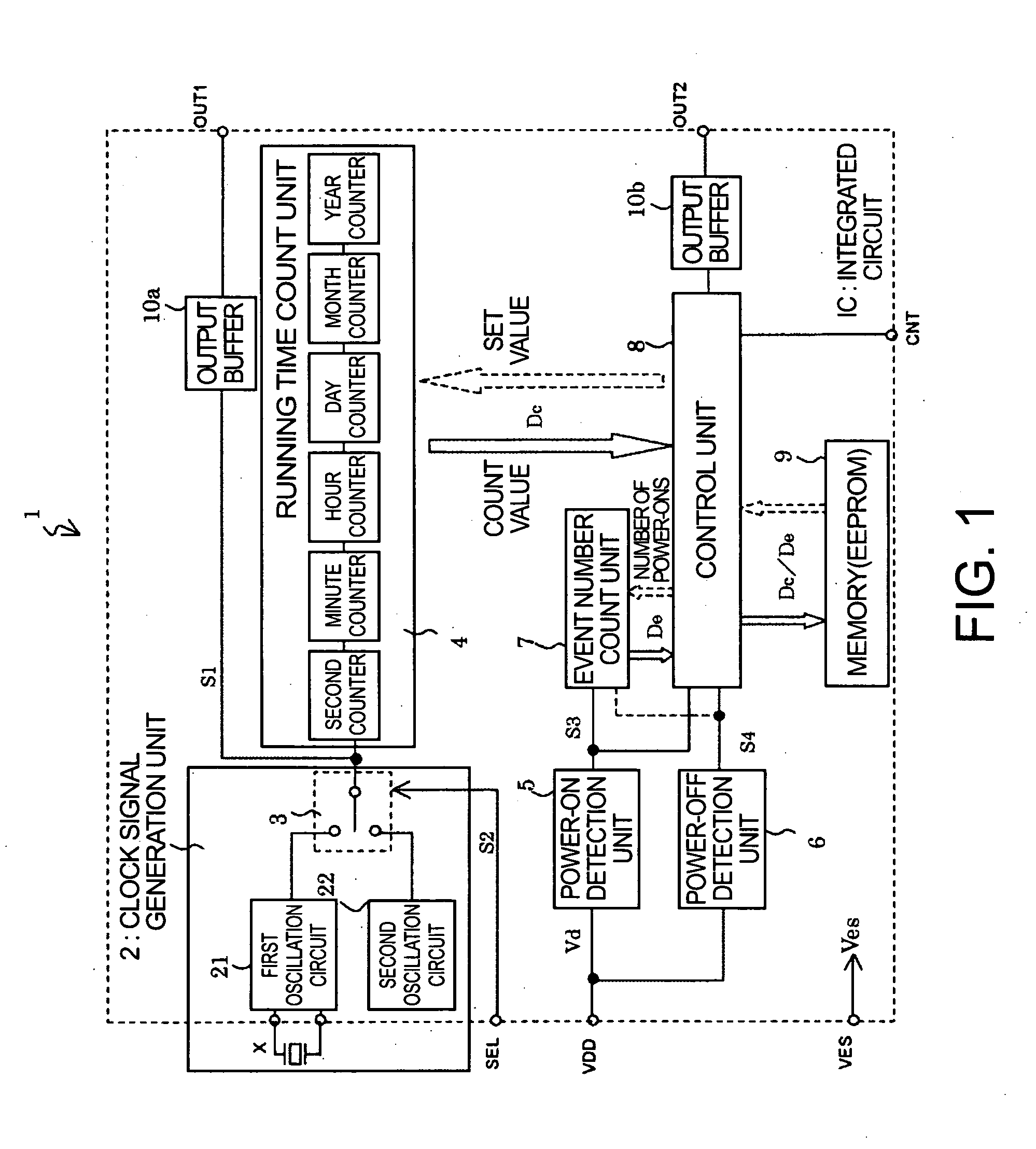
[0075] In synchronization with the start of work, the user powers on and drives the electronic apparatus. The first oscillation circuit 21 is selected by the oscillation circuit selection unit 3 in accordance with the external selection signal S2 (St...

embodiment 2

[0079] Next, operations of another example, Embodiment 2, will be described with reference to FIG. 7.

[0080]FIG. 7 is a flowchart for explaining the operation of Embodiment 2.

[0081] In Embodiment 2, at a power-on time of the electronic apparatus, the accumulated running time and the accumulated number of power-ons stored in the memory are set to the running time count unit 4 and the event number count unit 7, respectively, and the count operation starts from the respective initial values, and the running time and the number of power-ons accumulated up to a power-off time are stored in the memory.

[0082] When the user powers on and drives the electronic apparatus, the first oscillation circuit 21 is selected by the oscillation circuit selection unit 3 in accordance with the external selection signal S2 (Step ST21). Next, the power-on detection unit 5 detects the power-on and outputs the power-on detection signal S3 to the event number count unit 7 and the control unit 8 (Step ST22)....


PUM


Abstract

An oscillator operated with an external power source or an external save power source is provided comprising: a clock signal generation unit for generating and outputting a clock signal; a power-on detection unit for detecting the power-on of the external power source; a power-off detection unit for detecting the power-off of the external power source; a running time count unit for counting the running time from a time of the power-on detection signal being input to a time of the power-off detection signal being input; storage means for storing accumulated running time up to a power-on time of the external power source; and a control unit for reading the running time at the time of the power-off detection signal being input, reading the accumulated running time from the storage means, adding the running time to the accumulated running time, and storing the addition result as a new accumulated running time in the storage means.

Description

RELATED APPLICATIONS [0001] This application claims priority to Japanese Patent Application Nos. 2003-078779 filed Mar. 20, 2003 and 2004-057587 filed Mar. 2, 2004 which are hereby expressly incorporated by reference herein their entireties. BACKGROUND [0002] 1. Technical Field of the Invention [0003] The present invention relates to an oscillator capable of accumulating and storing the running time of an electronic apparatus and to an electronic apparatus using the oscillator. [0004] 2. Description of the Related Art [0005] Recently, various electronic apparatuses such as a personal computer, copier, etc., have widely utilized electronic parts or mechanical parts such as an oscillator, a display including a liquid crystal display (LCD), a memory, a central processing unit (CPU), etc. In general, these electronic apparatuses have their own expiration dates. When the expiration dates are passed, the electronic apparatuses are discarded without exception. However, there are problems t...

Claims


Application Information

Patent Timeline
IPC IPC(8): G04F10/00H03L1/00G04F10/02G07C3/04
CPCG04F10/00G07C3/04G04F10/02H03L1/00
Inventor ENDO, TAKASHIFUJII, YOICHI
Owner SEIKO EPSON CORP
Why Eureka
Try Eureka