Head module, liquid jetting head, liquid jetting apparatus, method of manufacturing head module, and method of manufacturing liquid jetting head

a technology of liquid jetting head and head module, which is applied in the direction of printing, inking apparatus, etc., can solve the problems of high manufacturing cost, high machining accuracy, and complicated structure of the fitting portion of the conduit plate, so as to prevent the generation of thermal stress, prevent the formation of nozzle formation surfaces between the head chips, and reduce the risk of nozzle failur

Inactive Publication Date: 2005-06-02
SONY CORP
View PDF0 Cites 34 Cited by
  • Summary
  • Abstract
  • Description
  • Claims
  • Application Information

AI Technical Summary

Benefits of technology

[0033] It is an object of the present invention to provide a head in which the positional accuracy of nozzle formation surfaces between head chips is high and which can be used also for a line head, without raising the manufacturing cost. It is another object of the present invention to provide a head in which liquid leakage arising from thermal stress is prevented, and the generation of thermal stress, warping or misregistration can be prevented from arising from temperature variations, and which is suitable for use in a line head.
[0034] It is a further object of the present invention to provide a head in which a cooling effect for head chips and inks can be obtained without providing a special cooling system, and the positional accuracy of nozzle formation surfaces between the head chips is high, and which can be used also for a line head.

Problems solved by technology

However, according to the technology disclosed in Japanese Patent Laid-open Nos. 2002-127427 and 2003-25579, the conduit plate is fitted into holes in which the head chips are arranged; therefore, the fitting portions of the conduit plate are complicated in structure and need a high machining accuracy, leading to a high manufacturing cost.
As a result, there is the problem of a high assembly cost.
The large size makes it necessary to adhere the head chips in the condition where flatness is secured over the whole region, leading to a high assembly cost.
Therefore, if any one of the head chips is failed, the head assembly as a whole would be unusable.
Besides, even a partial trouble in the head assembly needs replacement of the whole head assembly, resulting in a high repair cost.
The environment of such a high temperature adversely affects the performance, life, and troubles of the head chips which have semiconductor portions, and would cause denaturing of the ink in the common conduit.
Therefore, the conduit is repeatedly bent in the vertical direction and in the left-right direction, resulting in a complicated conduit.
With such a conduit, the passage resistance is so high that a hindrance is generated in smooth circulation of the ink and that it is impossible to obtain a sufficient cooling performance.
In addition, according to the technology disclosed in Japanese Patent Laid-open No. 2002-86695, the surface where the nozzle opening portion 472 is formed of the print head die 40 is projected from a first surface 301 of a support 30, as disclosed in FIG. 2 of Japanese Patent Laid-open No. 2002-86695; in the case of such a structure, the ink jetting surface is not a smooth surface, which is unfavorable.
However, in the structure in which head chips are adhered to a nozzle sheet provided with wiring pattern portions and electric drive power is supplied from the nozzle sheet to the head chips, a long-time driving causes the nozzle sheet to be heated by the heat generating resistors, whereby the nozzle sheet is deflexed or warped, and the flatness of the nozzle sheet is spoiled, which may lead to instable jetting of the ink.
However, in the case where the material constituting the nozzle sheet is a resin polymer having a high coefficient of linear expansion or in the case where a single nozzle sheet is provided with nozzles for all head chips and a plurality of head chips are joined to the nozzle sheet, as in Japanese Patent Laid-open Nos. 2002-127427 and 2003-25579, expansion or deflection of the nozzle sheet degrades the plain surface property of the head chips, thereby adversely affecting the jetting of the ink.
Particularly, the formation of a flat nozzle surface by adjusting the flatness degrees of a plurality of head chips is an important problem in adjusting the ink jetting direction, as above-mentioned.
Besides, in a printer head, the heat of the heat generating resistors at the time of printing is transferred to the members located in the surroundings of the head chips, resulting in thermal expansions due to temperature rise.
Particularly, when the members constituting the conduit are deformed under thermal stress or when the generation of thermal stress is repeated, the joint surfaces of the members constituting the conduit would be separated, possibly leading to leakage of the ink.
Namely, in a structure in which different members are fitted to each other, there would be the problems of the generation of thermal stress and warping in the members due to thermal expansion, misregistrations between the members, etc.

Method used


Image

  • Head module, liquid jetting head, liquid jetting apparatus, method of manufacturing head module, and method of manufacturing liquid jetting head
  • Head module, liquid jetting head, liquid jetting apparatus, method of manufacturing head module, and method of manufacturing liquid jetting head
  • Head module, liquid jetting head, liquid jetting apparatus, method of manufacturing head module, and method of manufacturing liquid jetting head

Examples


Embodiment Construction

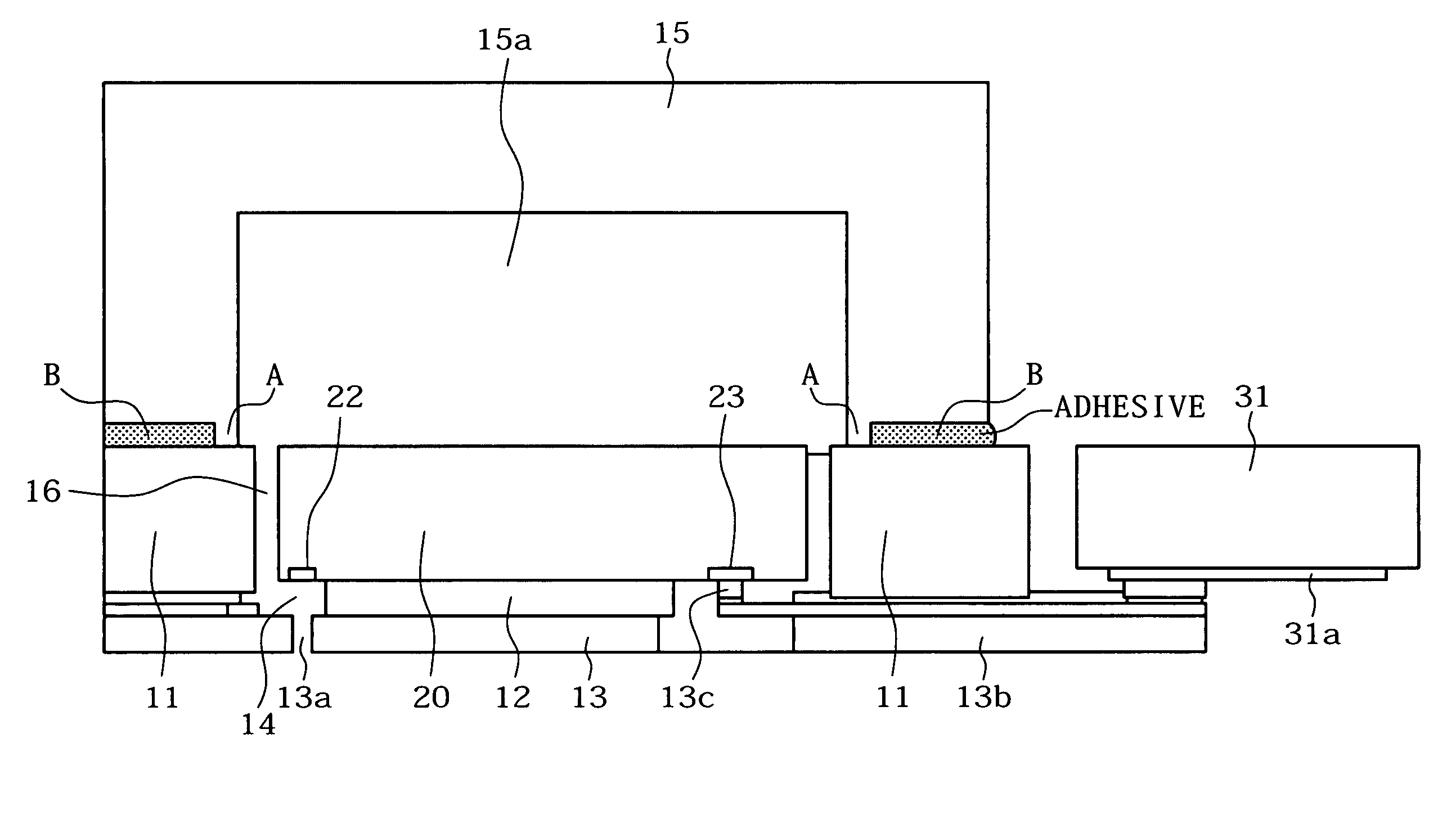
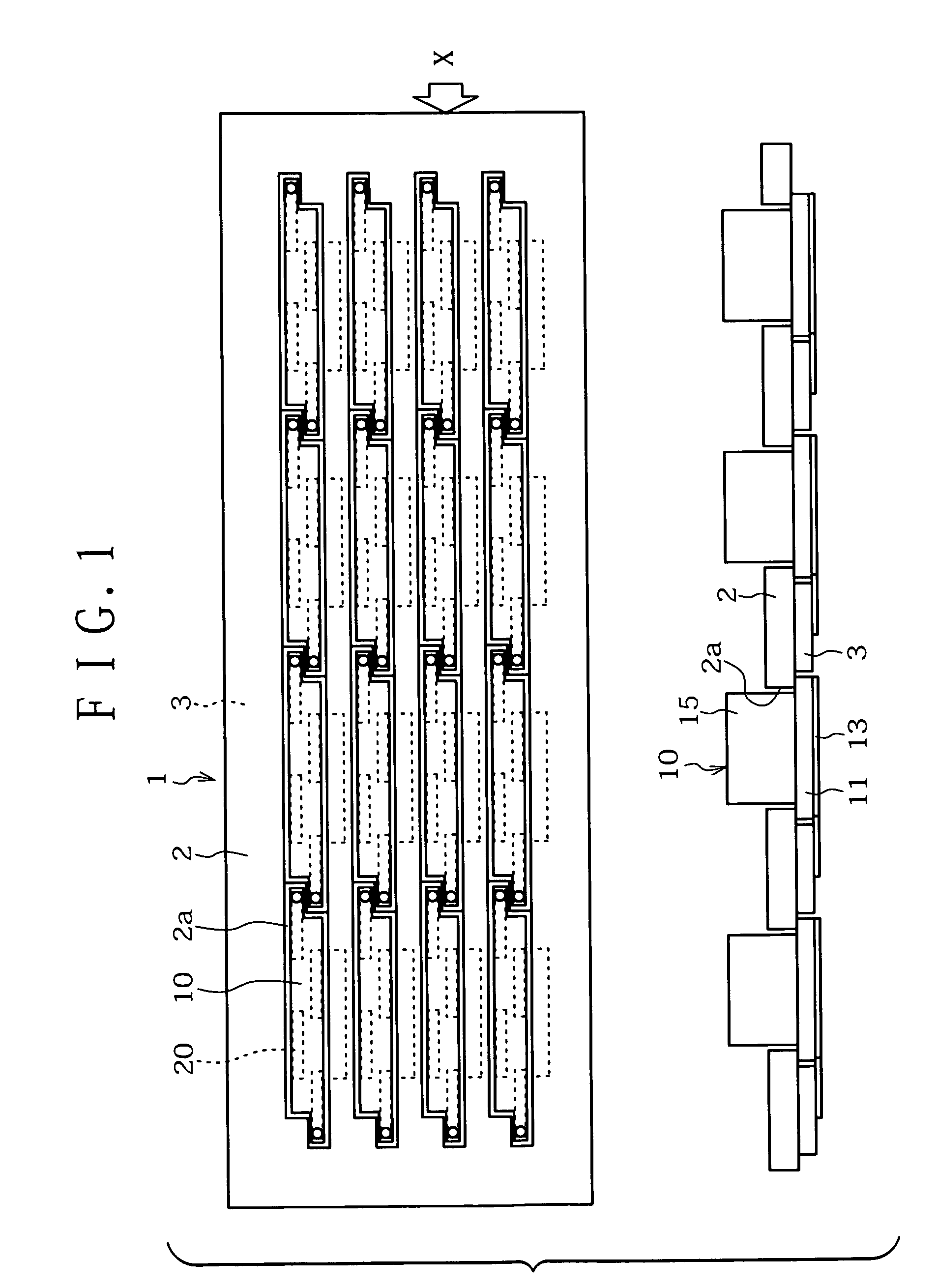
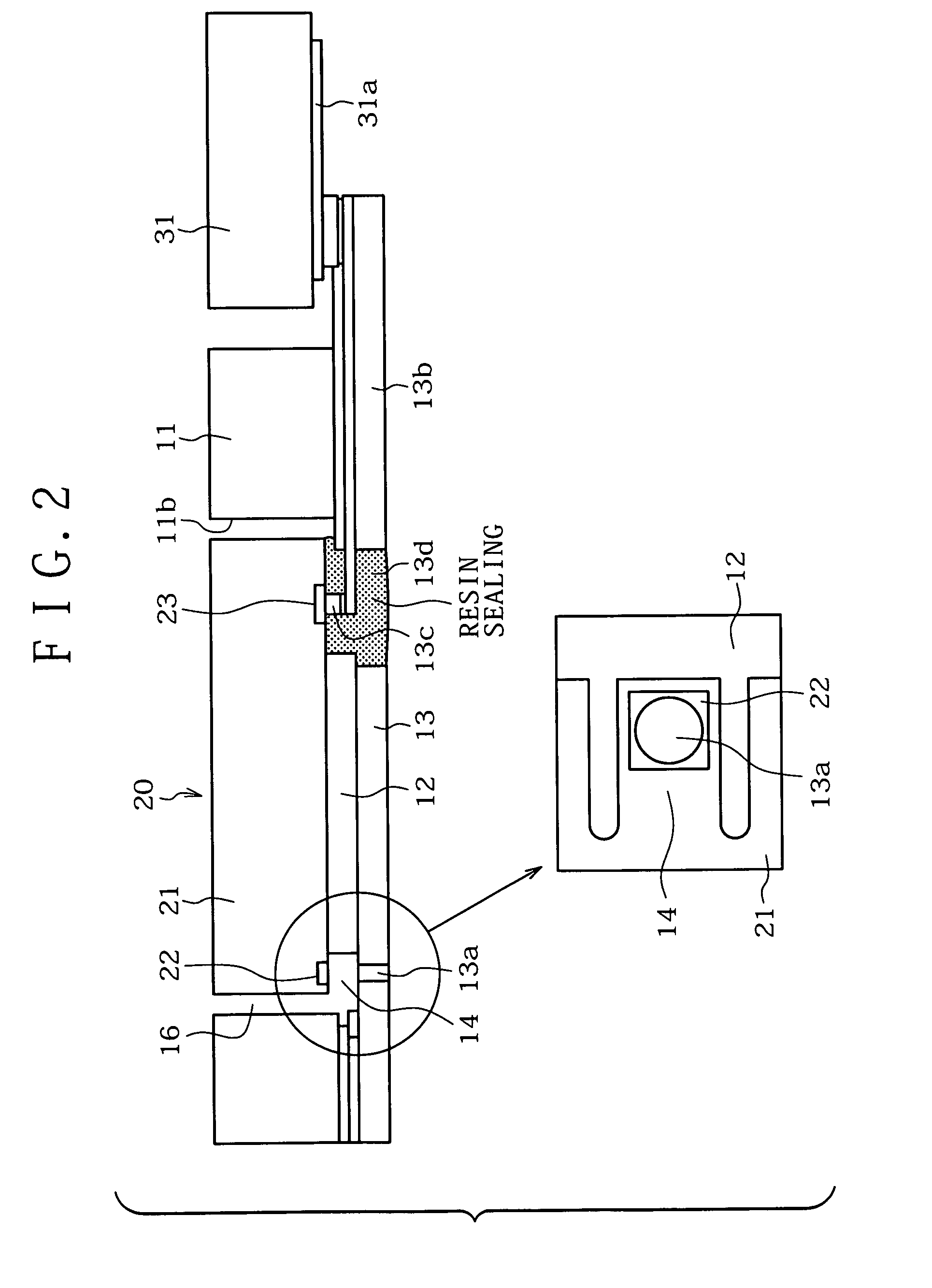
[0076] Now, one embodiment of the present invention will be described referring to the drawings. FIG. 1 shows a plan view showing a liquid jetting head 1 as one embodiment of the present invention, and a side view (sectional view) along arrow X. FIG. 2 shows a side sectional view and a bottom plan view, showing the configuration of a head chip 20 mounted in the liquid jetting head 1 and the vicinity thereof.

[0077] The liquid jetting head 1 is used as a head to be mounted in a liquid jetting apparatus (in this embodiment, a color line ink jet printer). As shown in FIG. 1, the liquid jetting head 1 is composed of a head frame 2, a printed wiring board 3, and a plurality of head modules 10. The four head modules 10 are connected in series in the longitudinal direction, in the plan view of FIG. 1, and four such assemblies (each of which include the four head modules 10 connected in series) are arranged in four rows. The four head modules 10 connected in series are used for printing in ...


PUM


Abstract

A head module includes a head chip provided with an array of heat generating elements, a nozzle sheet provided with nozzles, a barrier layer for forming ink liquid chambers, a module frame adhered to the nozzle sheet to thereby support the nozzle sheet and provided with a head chip arranging hole for arranging the head chip therein, and a buffer tank which is so disposed as to cover the head chip arranging hole from a surface, on the opposite side of the surface of adhesion to the nozzle sheet, of the module frame and which is for forming a common liquid conduit communicated with all the ink chambers of the head chip.

Description

BACKGROUND OF THE INVENTION [0001] The present invention relates to a head module used as a head for jetting a liquid in a liquid jetting apparatus such as an ink jet printer, etc., a liquid jetting head, methods of manufacturing these, and the liquid jetting apparatus. [0002] Conventionally, the ink jet printer has been known as one example of liquid jetting apparatus, and a variety of technologies have been disclosed in relation to the printer head of the ink jet printer. [0003] For example, Japanese Patent Laid-open Nos. 2002-127427 and 2003-25579 each disclose a technology for assembling a line head from a plurality of head chips. [0004] In the technology disclosed in Japanese Patent Laid-open Nos. 2002-127427 and 2003-25579, a single nozzle forming member formed of nickel by electroforming is provided with a multiplicity of nozzles (ink jet ports). A plurality of head chips are adhered to the single nozzle forming member. Furthermore, a head frame provided with such holes as to...

Claims


Application Information

Patent Timeline
Patent Type & Authority Applications(United States)
IPC IPC(8): B41J2/05B41J2/14B41J2/155B41J2/16
CPCB41J2/14024B41J2/14072B41J2/155B41J2202/20B41J2/1623B41J2/1631B41J2/1634B41J2/1603B41J2/14056
Inventor TANIKAWA, TORUKAYABA, SHINJIANDO, NAOSHITAKAKURA, MASAYUKIANDO, MAKOTOHORII, SHINICHIMURAKAMI, TAKAAKITOMITA, MANABU
Owner SONY CORP
Why Eureka
Try Eureka