Film image scanning system and light source unit for scanning a film

a film image and scanning system technology, applied in the field of film image scanning system and light source unit for scanning a film, can solve the problems of inability to ensure the dynamic range of the shadow area of the film image, the loss of image sharpness, and the inability to obtain a high image quality, so as to improve the dynamic range, eliminate the difference in sensitivity of each color image plane, and improve the resolution of each color plan

Inactive Publication Date: 2005-06-02
NIKON CORP
View PDF5 Cites 8 Cited by
  • Summary
  • Abstract
  • Description
  • Claims
  • Application Information

AI Technical Summary

Benefits of technology

[0029] According to the present invention, the RGB wavelength (narrow band) of the light source unit that emits light toward the film is located in the vicinity of the film dye (CMY) and the cross point of each spectral distribution of the filter of the CCD. Therefore, it is possible to enhance the resolution of each color plane, to greatly improve the dynamic range by reserving the S/N of each image data which is read in after being subjected to color separation

Problems solved by technology

However, when the digital camera or the like captures the image by irradiating the film with white light source, a conventional system is hard to obtain a high image quality that can satisfy users in view of the resolution and the dynamic range (reproducible tonal range).
In conventional arts, when using a digital camera with a color area CCD to photograph a film by white light source irradiation, there exist problems as follows:
Therefore, an interpolation processing is needed, and the image will lose its sharpness.
Secondly, AE

Method used


Image

  • Film image scanning system and light source unit for scanning a film
  • Film image scanning system and light source unit for scanning a film
  • Film image scanning system and light source unit for scanning a film

Examples


first embodiment

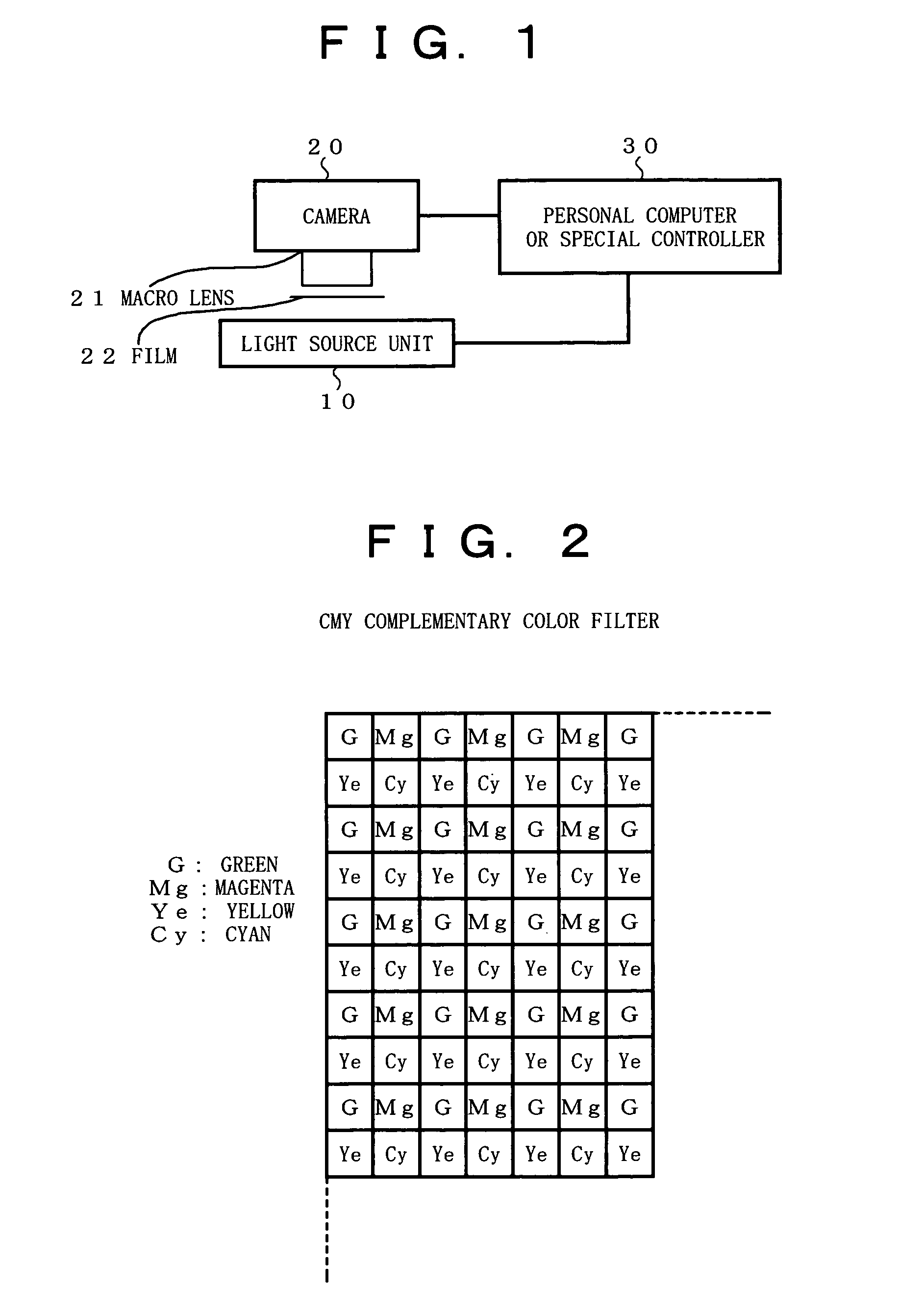
[0047]FIG. 1 shows the present invention. FIG. 1 shows a light source unit 10, a camera 20 (e.g. a digital camera) or an area CCD (CMY), a macro lens 21, a film 22 as a subject to be scanned, and a personal computer 30 or a special controller.

[0048] The color area CCD mounted on the digital camera shown in FIG. 1 is provided with a complementary color filter or a primary color filter.

[0049]FIG. 2 is an explanatory view showing a typical CMY complementary color filter.

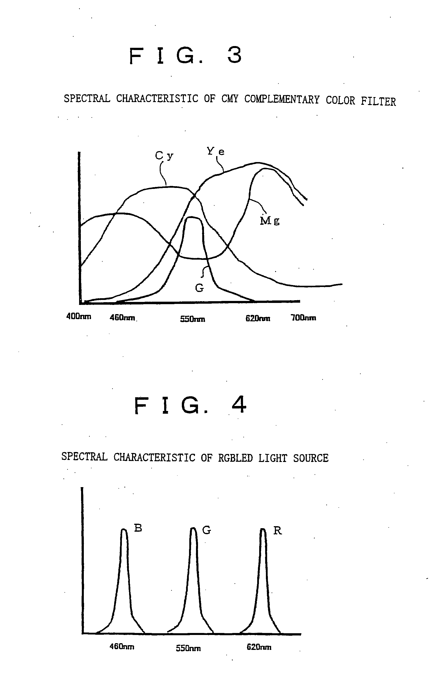
[0050]FIG. 3 is a view showing the spectral characteristics of the CMY complementary color filter shown in FIG. 2. In FIG. 2 and FIG. 3, “G” means green, “Mg” means magenta, “Ye” means yellow, and “Cy” means Cyan.

[0051] Furthermore, the light source unit 10 in FIG. 1 includes a three-color LED light source with R (red), G (green), and B (blue) light (hereinafter referred to as an RGBLED light source) having the spectral characteristics of narrow band.

[0052]FIG. 4 is a view showing the spectral characteristics of the...

third embodiment

[0149] The process of the third embodiment will be described briefly as follows.

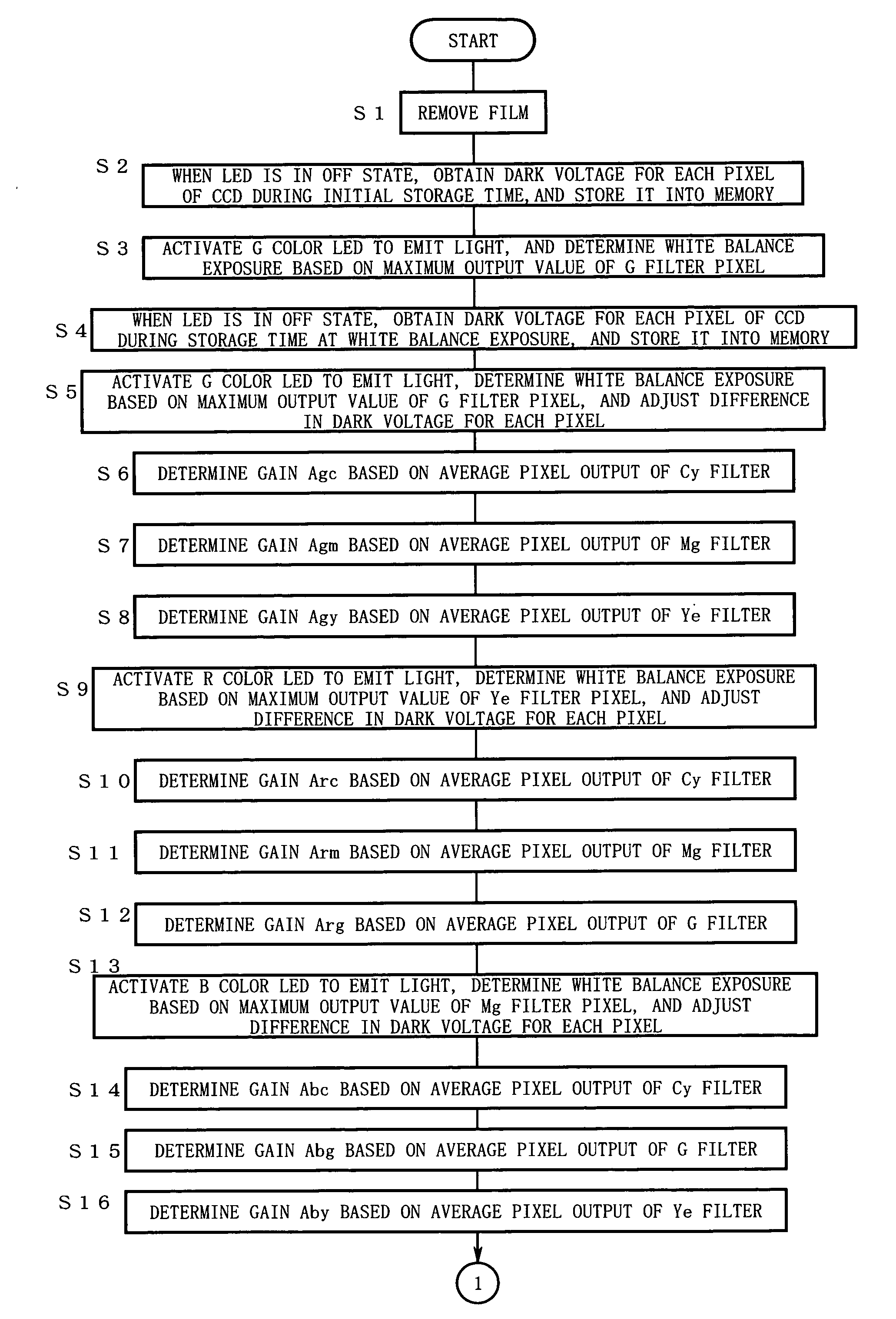
[0150] The light source unit 10 is equipped with a white balance mode (color negative mode and normal mode), an R lighting switch, a G lighting switch, and a B lighting switch.

[0151] The light source unit 10 is set to the white balance mode and emits respective illumination light beams. In this case, when the amount of each color light for the white balance is determined in advance, light of each color is emitted simultaneously with the required amount of light emission. In the case of the color negative mode, the white balance exposure with increased amount of the blue light and the green light is performed.

[0152] The camera 20 photographs the above-mentioned white balance light.

[0153] Next, a film 22 is set in place.

[0154] Next, the light source unit 10 emits R light and the camera 20 photographs the film.

[0155] Next, the light source unit 10 emits G light, B light, and IR light in sequence and th...

second embodiment

[0159] If the camera 20 is connected to a printer, the film image can be printed thereby as in the

[0160] Hereinafter, the light source unit 10 will be described.

[0161]FIG. 15 is an explanatory view showing an embodiment of the light source unit 10.

[0162] As shown in FIG. 15, the light source unit 10 includes a power unit 12, an electrical board 13, an LED chip substrate 14, and a diffusing panel 15. An original film is held by a film-holder 16. In addition, on the film-holder 16 there is a mask 17 with a window 18. The mask 17 prevents the light, which is not transmitted through the film, from entering into the macro lens of the camera 20. As described above, the diffusing panel 15 allows the light from the LED chip substrate 14 to be emitted evenly, to prevent the film image scanned by the color area CCD of the camera 20 from being granular (phenomenon that makes the image looks rough). Moreover, besides the diffusing panel, any member that is able to allow the light from the LED...


PUM


Abstract

When scanning a film image, a difference in sensitivity between image planes corresponding to respective colors of light caused by color CCD filters is eliminated, and resolution and dynamic range of the scanned image are greatly improved. Therefore, the system includes: a light source unit for scanning a film, which emits light of a plurality of narrow bands toward a film as a single band or in a combination thereof; a digital camera scanning the light transmitted through the film with a color CCD, producing an image plane of each color of the light based on output data from the color CCD where each color of the light has been subjected to a sensitivity correction, and producing a film image by combining the respective image planes produced; and a controller connected to the light source unit and the digital camera to control the light source unit and the digital camera.

Description

BACKGROUND OF THE INVENTION [0001] 1. Field of the Invention [0002] The present invention relates to a film image scanning system and a light source unit for scanning a film. More specifically, the present invention relates to a film image scanning system and a light source unit for scanning a film suited for photographing a negative film or a positive film by a digital camera or a TV camera equipped with a color area CCD. [0003] 2. Description of the Related Art [0004] It is convenient if a digital camera or the like can be used for easily and quickly capturing film images to be posted on the WWW (World Wide Web). However, when the digital camera or the like captures the image by irradiating the film with white light source, a conventional system is hard to obtain a high image quality that can satisfy users in view of the resolution and the dynamic range (reproducible tonal range). [0005] A technique for photographing a negative or positive film by an electric camera is disclosed i...

Claims


Application Information

Patent Timeline
IPC IPC(8): G06T1/00G03B27/54G06T3/00H04N1/00H04N1/04H04N1/195H04N1/21H04N5/253H04N9/07H04N9/11H04N101/00
CPCH04N1/0282H04N1/0289H04N1/195H04N2201/0404H04N9/045H04N9/11H04N9/735H04N1/19594H04N23/88
Inventor HOKOI, HAYATO
Owner NIKON CORP
Why Eureka
Try Eureka