
Switchable latching-type faraday rotator

a technology of latching and rotators, which is applied in the direction of polarising elements, magnetic bodies, instruments, etc., can solve the problems of inability to control or switch the rotation angle, incomparable reliability, and the prior art switchable faraday rotator cannot meet these requirements

Inactive Publication Date: 2005-06-02
SHANGHAI PRIMANEX PHOTOELECTRIC TECH +1
View PDF1 Cites 4 Cited by
  • Summary
  • Abstract
  • Description
  • Claims
  • Application Information

AI Technical Summary

Benefits of technology

[0023] The objective of the present invention relates to providing a switchable latching-type Faraday rotator having low electrical power consumption, small physical profile, as well as reliable latching capability.
[0025] The present invention optimizes the semi-hard magnets design so that the semi-hard magnets can generate maximum magnetic field at the location of magneto-optic crystal. This optimized design lows driving current and voltage, improves latching reliability and reduces physical profile of the Faraday rotator.
[0027] After all these efforts, the present invention can bring the driving voltage down to 4V and driving current down to 55 mA. The present invention also improves latching reliability of the Faraday rotators. The Faraday rotators made with present invention can latch in their original status for a few weeks in the 85° C. oven.

Problems solved by technology

Fixed rotators use fixed magnetic field or permanently magnetized magneto-optic materials, so that the rotation angle is fixed and cannot be controlled or switched.
Compared with opto-mechanic technologies, the switchable or variable magneto-optical devices have no moving-parts and hence have incomparable reliability.
However, prior art switchable Faraday rotators cannot meet these requirements listed above.
Some Faraday rotators do switch and latch, but require too much driving current (usually large than 1 A) to prevent them from being used in practical optical systems.
The dual difficulties of lack of stable latching capability and the need for high switching current has precluded magneto-optic (Faraday rotator) switches from capturing a major share of the applications for optical switches.
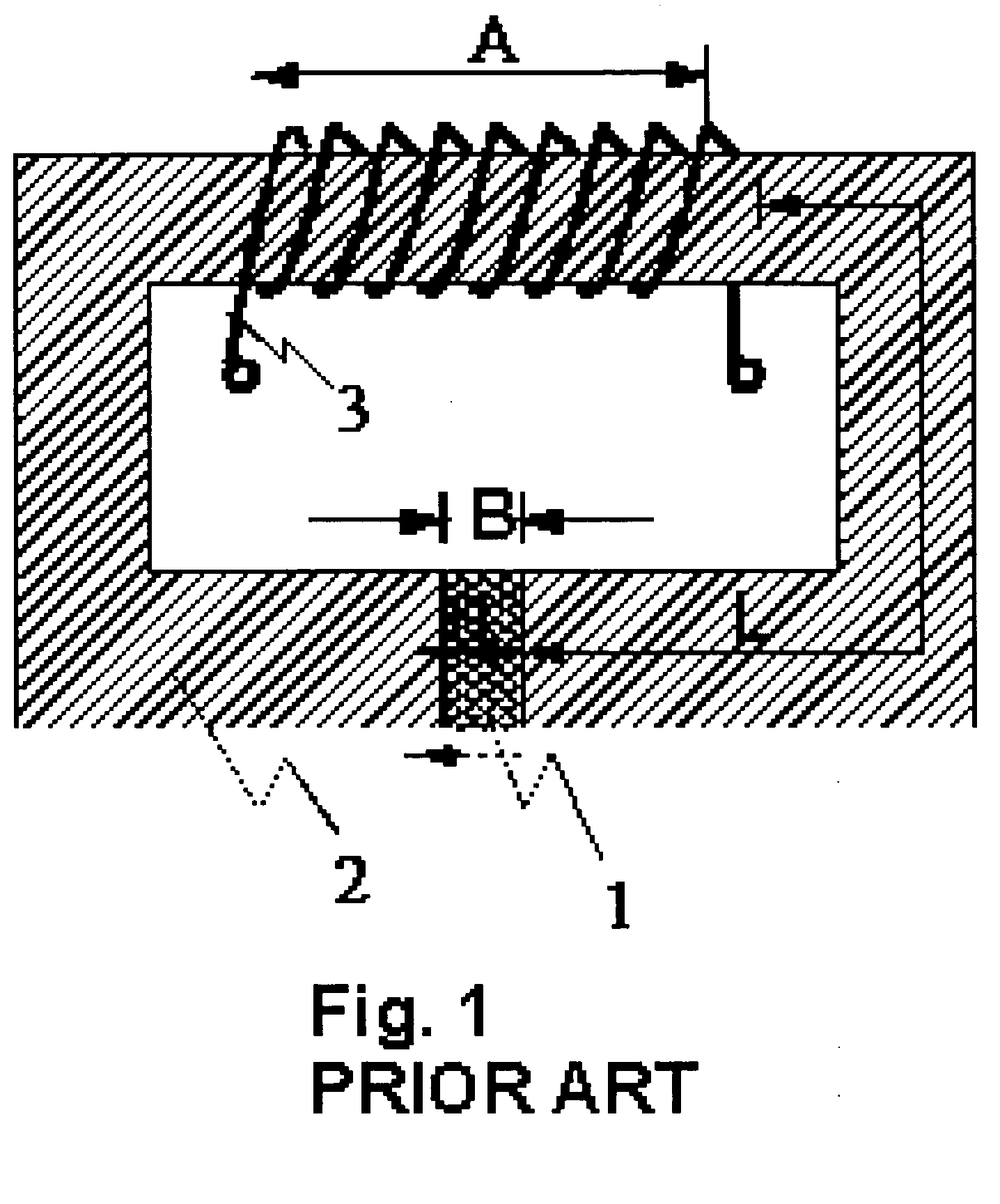
However, the Faraday rotator depicted in FIG. 1 has major drawbacks, including the following: First, at the location of the magneto-optic material, the major component of the magnetic field is perpendicular to the light traveling path, hence most of the magnetic energy cannot contribute to Faraday rotation.
Second, a significant portion of the magnetic energy is consumed and wasted by the long arms of the electromagnet.
Third, since most of the magnetic field is just wasted, it requires very large driving current to magnetize and latch the magneto-optic material.
Fourth, this design has large asymmetrical physical profile and it is unsuitable to use it into the compact optical devices.
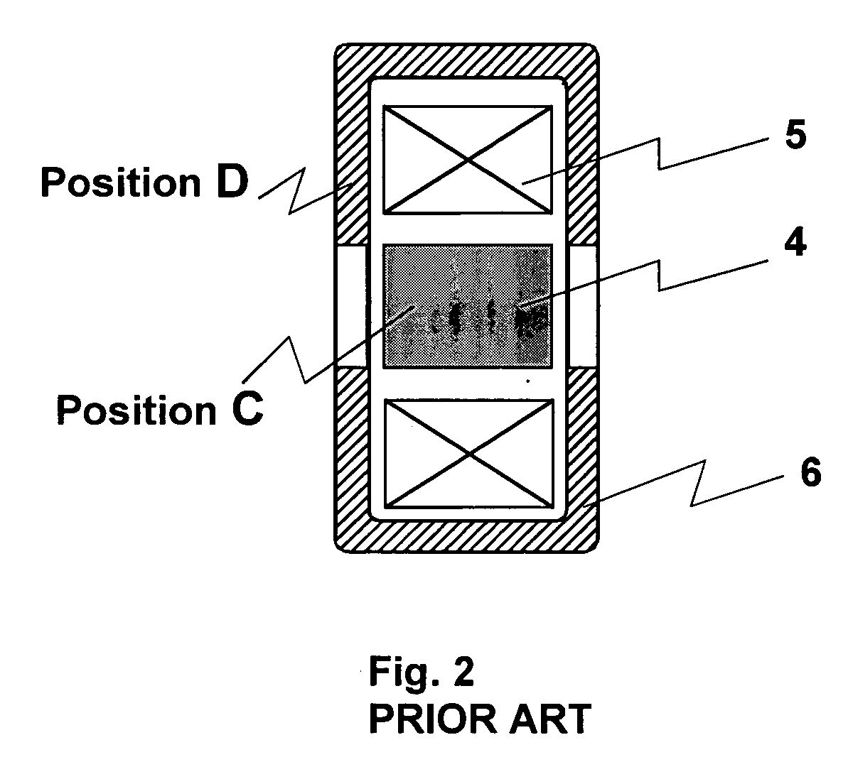
Thus, this device has the disadvantage of not effectively magnetizing the hollow yoke, hence needs very large current to achieve latching functionality.
Although there is substantial improvement in driving current compared with FIG. 1 and FIG. 2 (needs 3 Amps driving current), the driving current (large than 100 mA) is still too high for optical communication applications.
Most of the magnetic energy is just wasted.
All these problems listed above for FIGS. 3 and 4 not only affect the driving current, but also affect the latching reliability.
Since the magnetic field at the location of magneto-optic crystal is not strong enough, the status of the magneto-optic crystal maybe unstable at high temperature (85° C.).

Method used


Image

  • Switchable latching-type faraday rotator
  • Switchable latching-type faraday rotator
  • Switchable latching-type faraday rotator

Examples


Embodiment Construction

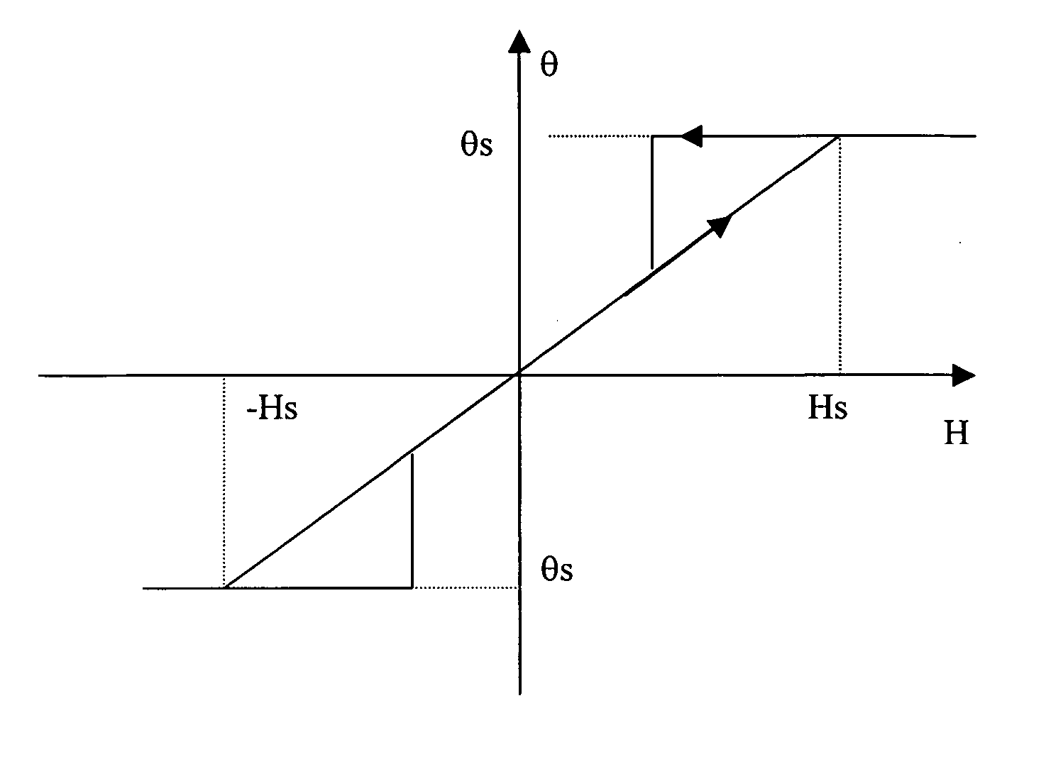
[0041] Magneto-optic material is the core material for the Faraday rotators. FIG. 5 depicts a typical magnetizing and demagnetizing curve of magneto-optic material. H is the external magnetic field which is applied to parallel to the light traveling path. Hs is usually called as “saturation magnetic field” or simply as “saturation point”, where the magneto-optic crystal is saturated.

[0042] To use the magneto-optic crystal in a switchable Faraday rotator, it is necessary to drive the magneto-optic crystal beyond two saturation points, Hs and −Hs. To be a latching type Faraday rotator, it is also necessary to provide sustainable magnetic field which is strong enough to drive the magneto-optic crystal into saturation region and reliably hold the saturation status. The semi-hard magnetic material is an ideal candidate for this application. The semi-hard magnetic material has very low coercive force (Hc5000 Gauss) so that it can produce strong magnetic field in its surrounding region af...


PUM

PropertyMeasurementUnit
resistanceaaaaaaaaaa
control voltageaaaaaaaaaa
temperatureaaaaaaaaaa

Abstract

The present invention relates to the. use of optimized magnet design, magnetic circuit design and wire coil design to improve latching reliability and reduce driving current for the switchable Faraday rotator devices. The geometrical parameters of semi-hard magnet are optimized to produce maximal magnetic field at the location of magneto-optic crystal and hence improve latching reliability and reduce driving current. The wire coil is optimized in coil length, wire gauge, and number of turns to produce most efficient energy transfer and hence reduce driving current and driving voltage. To reduce magnetic energy loss, soft magnetic material is included to form a magnetic conductive close loop and further reduces driving current requirements.

Description

BACKGROUND [0001] 1. Technical Field [0002] The present invention relates to the general field of switchable latching Faraday rotators and, more particularly, relates to enhancing the switching and latching reliability, and reducing driving current and voltage. [0003] 2. Description of Related Art [0004] Faraday rotation is a magneto-optic effect in which the plane of polarization of polarized light is caused to rotate by passage through a magneto-optic material to which is applied an external magnetic field. The combination of magneto-optic material and a means for application of an external magnetic field is denoted as a “Faraday rotator”. [0005] The rotation angle, θ, denotes the angle through which the plane of polarization is rotated by the magneto-optic material. Typically, θ is approximately proportional to the intensity of the magnetic field applied to the magneto-optic material in the direction of propagation of the light through the material as in Eq. 1. θ=K−H∥  Eq. 1 in ...

Claims


Application Information

Patent Timeline
Patent Type & Authority Applications(United States)
IPC IPC(8): G02F1/09H01F7/20
CPCH01F7/20G02F1/09
Inventor XIANG, QIANGSHENGHUANG, GANGLIN, XIANGZHI
Owner SHANGHAI PRIMANEX PHOTOELECTRIC TECH
Learn More