
Optical transmission method and system

Inactive Publication Date: 2005-06-02
NAT INST OF INFORMATION & COMM TECH
View PDF8 Cites 36 Cited by
  • Summary
  • Abstract
  • Description
  • Claims
  • Application Information

AI Technical Summary

Benefits of technology

[0008] According to the invention, a phase-modulated signal generated through complete modulation is carried by one of the two orthogonal polarizations and an optical carrier is carried by the other, and therefore the optical receiver can receive a signal without using an optical PLL. This makes the configuration of an optical receiver much simpler.

Problems solved by technology

Under such circumstances, an optical receiver is forced to operate an optical PLL depending on a small amount of optical carriers and therefore demodulating operation becomes unstable.

Method used


Image

  • Optical transmission method and system
  • Optical transmission method and system
  • Optical transmission method and system

Examples


Embodiment Construction

[0015] Explanatory embodiments of the invention are explained below in detail with reference to the drawings.

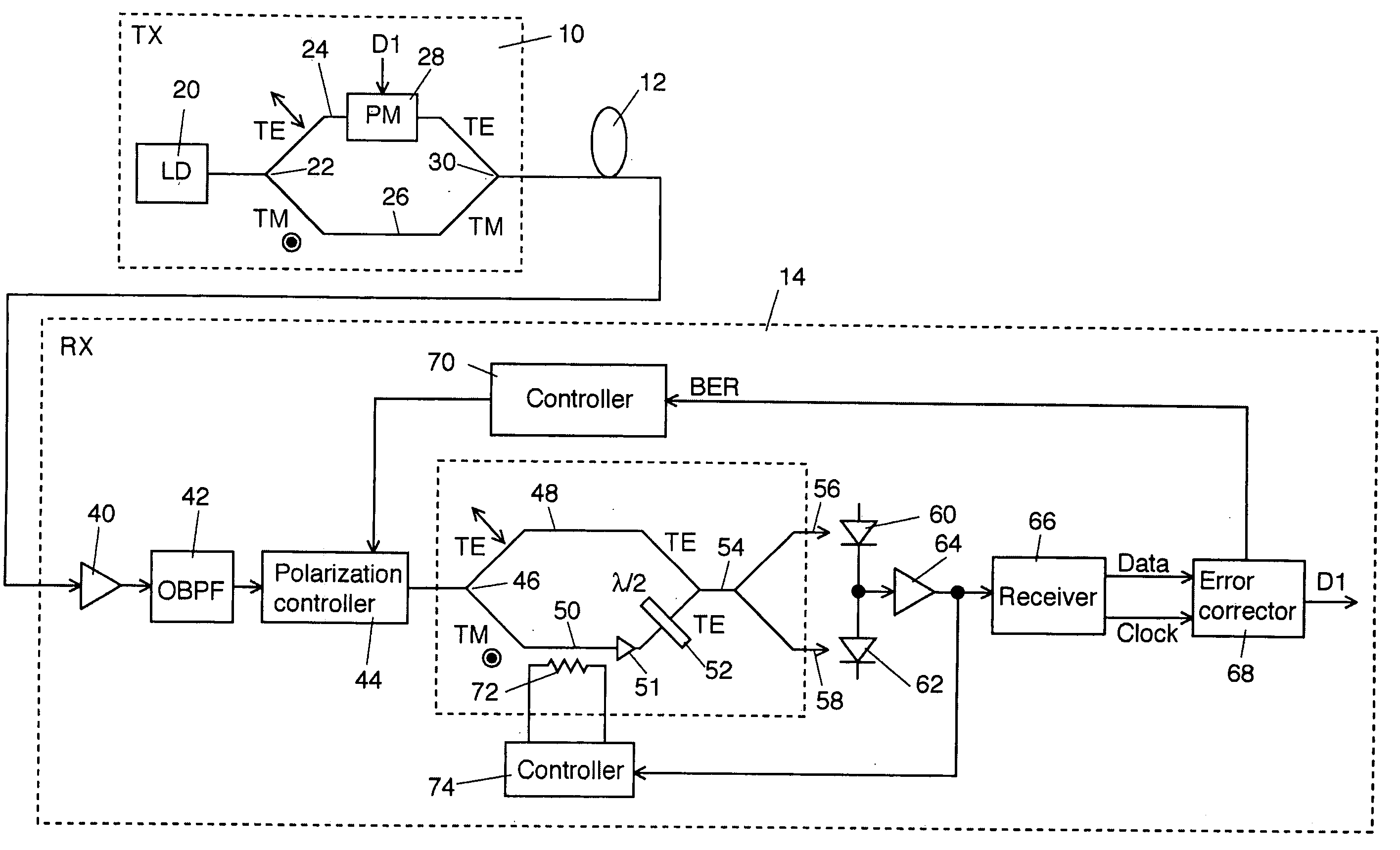
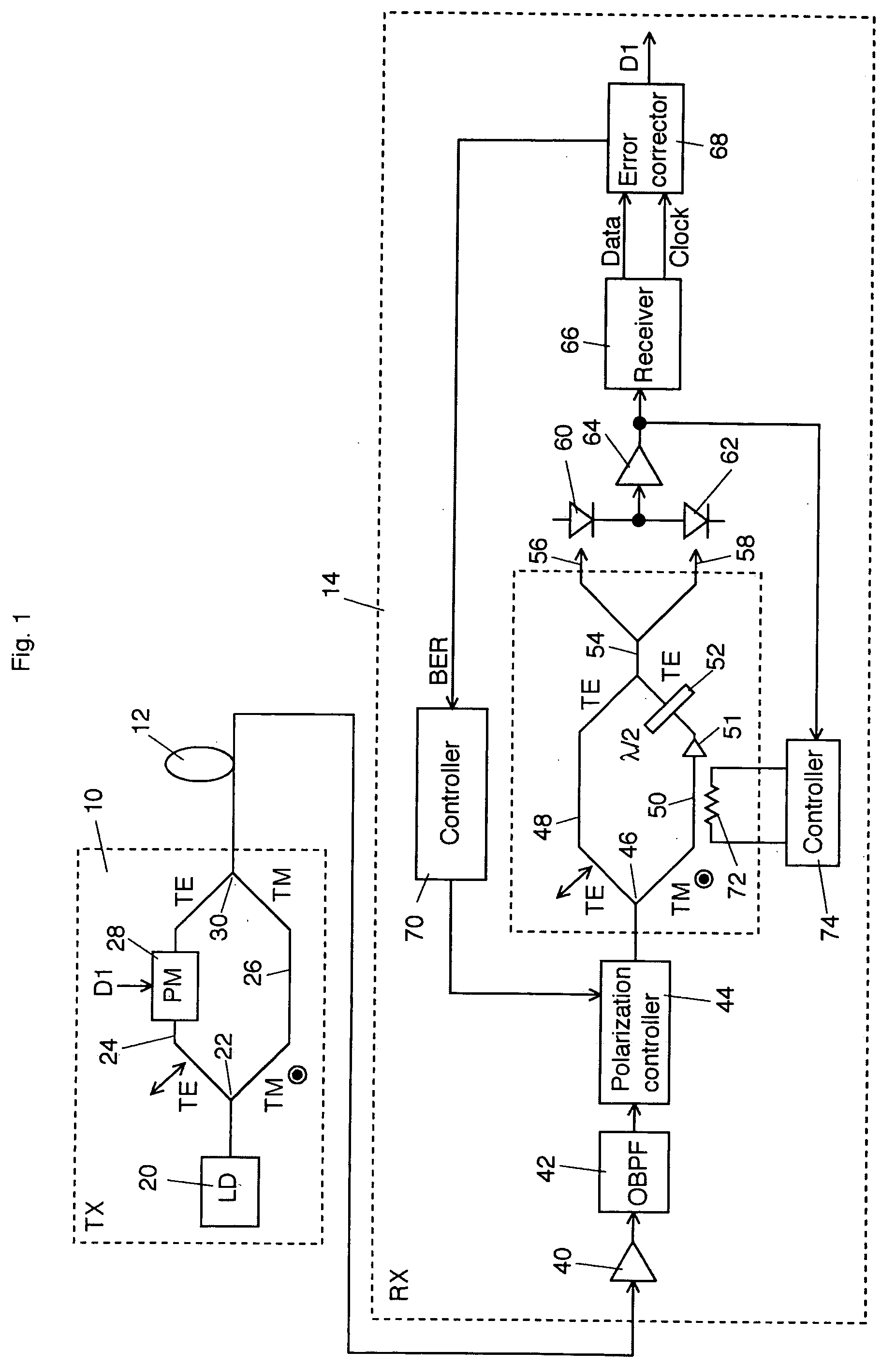
[0016]FIG. 1 shows a schematic block diagram of a first explanatory embodiment according to the invention. An optical transmitter 10 outputs a PSK signal light into an optical transmission line 12. The PSK signal light having transmitted in the optical transmission line 12 enters an optical receiver 14.

[0017] The configuration and operation of the optical transmitter 10 is explained below in detail. A laser light source 20 outputs a continuous wave laser light (or pulse laser light) of a signal wavelength Xs. A polarization beam splitter 22 splits an output light from the laser light source 20 into two orthogonal polarization components, i.e. a TE-wave and a TM-wave, and applies one component, e.g. the TE-wave, to an arm 24 and the other, e.g. the TM-wave, to an arm 26. A phase modulator 28 disposed on the arm 24 is to binary-modulate the optical phase of the TE-wave from t...


PUM


Abstract

An optical transmitter splits a linear polarization optical carrier into a TE wave and a TM wave. One of the TE wave and the TM wave is phase-modulated with a transmission data so as to generate a phase-modulated signal. The phase-modulated signal and the other one of the TE wave and the TM wave are coupled with a linear polarization and output into an optical transmission line. An optical receiver splits a light input from the optical transmission line into the TE wave and the TM wave. The TM wave or TE wave is converted into the TE wave or TM wave to interfere with the TE wave or TM wave. The interfered signal light is converted into an electric signal for restoration of the data.

Description

CROSS REFERENCE TO RELATED APPLICATIONS [0001] This application claims priority to Japanese Patent Application No. 2003-401473, filed Dec. 1, 2003, the entire contents of which are incorporated herein by reference. FIELD OF THE INVENTION [0002] This invention generally relates to an optical transmission method and system to use an optical phase modulation. BACKGROUND OF THE INVENTION [0003] In optical phase modulation, the efficiency of frequency utilization per bit rate is high. PSK (Phase Shift Keying) and DPSK (Differential Phase Shift Keying) are well known as such optical phase modulation in the art. [0004] In complete modulation, it is necessary to dispose an optical phase locked loop (PLL) circuit for regenerating an optical carrier on a receiving side and moreover an optical Costas loop is required for the optical PLL. An optical PLL in an optical receiver in homodyne detection is described in “Balanced phase-locked loops for optical Homodyne receivers: Performance Analysis,...

Claims


Application Information

Patent Timeline
IPC IPC(8): H04B10/07G02F1/01H04B10/2507H04B10/516H04B10/556H04B10/572H04B10/61
CPCH04B10/5051H04B10/5053H04B10/5055H04B10/69H04B10/67H04B10/677H04B10/548
Inventor MIYAZAKI, TETSUYA
Owner NAT INST OF INFORMATION & COMM TECH
Learn More