Electrophotographic photosensitive member and judging method for interference fringes caused by electrophotographic photosensitive member

a photosensitive member and electrophotography technology, applied in the field of electrophotography photosensitive members, can solve the problems of deteriorating image quality, undulating intensity of reflected light, and often generated optical interferen

Inactive Publication Date: 2005-06-02
FUJI ELECTRIC CO LTD
View PDF2 Cites 9 Cited by
  • Summary
  • Abstract
  • Description
  • Claims
  • Application Information

AI Technical Summary

Benefits of technology

[0028] The invention has been made in consideration of the aforementioned situation, and is to provide a judging method (discriminating method) for interference fringes of an electrophotographic photosensitive member, capable of exactly confirming presence/absence of interference fringes, on a photosensitive member which is provided, on a roughened surface of a substrate, with an undercoat layer containing a metal oxide and formed by coating with a certain film t

Problems solved by technology

In such a dry-process electrophotographic apparatus, optical interference is often generated because of the use of a coherent (monochromatic) laser beam as the exposure light source.
An interference fringe pattern, such as a moiré pattern or a zebra pattern formed on a printed output image, deteriorates the image quality.
The interference fringe pattern is generated because monochromatic light reflected at a top surface of a photosensitive layer interferes with light reflected at interfaces of internal layers, including a surface of a substrate, causing optical interference due to unevenness in the layer thickness, which leads to an undulating intensity of the reflected light.
However, they also found that the fringes cannot be eliminated to a satisfactory level by simply working the conductive substrate to a predetermined surface roughness.
Such a method has the drawbacks of requiring time and labor and being unable to provide a result immediately.
Furthermore, there is another drawback in that the interference fringes cannot always be prevented by the roughening the surface of just the conductive substrate, because s conditions inducing the interference fringes are also affected by the photosensitive layer formed on the undercoat layer.
Such reflected a component significantly influences the optical interference.
The optical intensity becomes stronger in such superposing position and weaker in a non-superposing position thereby generating an unevenness in the optical intensity and causi

Method used


Image

  • Electrophotographic photosensitive member and judging method for interference fringes caused by electrophotographic photosensitive member
  • Electrophotographic photosensitive member and judging method for interference fringes caused by electrophotographic photosensitive member
  • Electrophotographic photosensitive member and judging method for interference fringes caused by electrophotographic photosensitive member

Examples


example 1

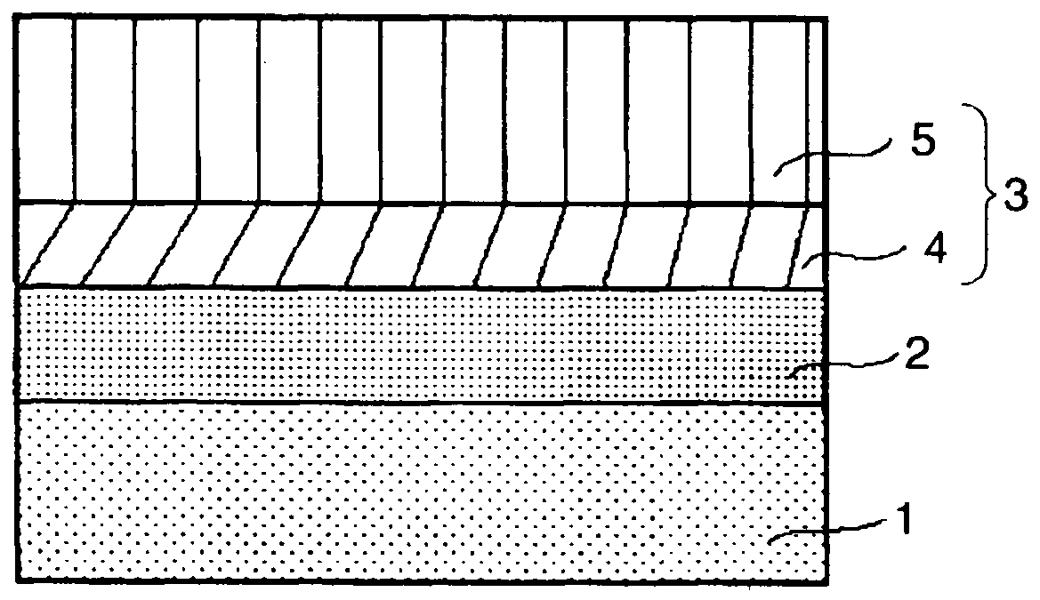
(Surface Roughening of Substrate)

[0085] A surface of a cylindrical aluminum conductive substrate, employed as the conductive substrate, was sand blasted to form a rough surface having a reflectance Isb=13.6%, an average surface roughness Ra (JIS)=0.35 μm and a maximum surface roughness Rmax (JIS)=2.7 μm. The reflectance Isb is a ratio (%) of a surface reflectance of a roughened substrate and a surface reflectance of a mirror-surface treated plain pipe, and was measured with a reflectance measuring apparatus 16 as shown in FIG. 16, MCPD-200 manufactured by Union Giken Co. The surface roughness was measured by SURFCOM (trade name, manufactured by Tokyo Seimitsu Co.) with a reference length of 0.8 mm and a measuring length of 4 mm.

(Formation of Undercoat Layer)

[0086] Then, an undercoat layer is provided on the surface of the conductive substrate roughened by the sand blasting. The undercoat layer is produced by applying a coating liquid prepared by dispersing 1.8 parts by weight o...

example 2

[0090] An organic electrophotographic photosensitive member was prepared in the same manner as in Example 1, except that the charge transport layer employed in Example 1 was changed to a film thickness of 18 μm.

example 3

[0091] An organic electrophotographic photosensitive member was prepared in the same manner as in Example 1, except that the charge transport layer employed in Example 1 was changed to a film thickness of 14 μm.


PUM


Abstract

In an electrophotographic apparatus (e.g., a photocopier or laser printer), an electrophotographic photosensitive member (image-forming part) has a metal substrate roughened on its surface, a metal oxide-containing undercoat layer on the substrate, and an organic photosensitive layer over the undercoat. A coherent light source (e.g., laser) can cause interference fringes that degrade the printed image. Interference fringes are judged (or predicted) as follows: The surface reflectance is measured at intervals over the spectral width of the light source. The measured surface reflectance is corrected, using a mirror-surface conductive substrate as a reference, to obtain a reflectance of the photosensitive member. The reflectance is subjected to a discrete Fourier transformation, which generates a power spectrum, over the spectral width of the light source, from the reflectance as a function of the wavelength. Interference fringes are judged from the maximum peak value in the power spectrum, as compared to a predetermined value.

Description

CROSS-REFERENCE TO RELATED APPLICATION [0001] The Applicant claims the foreign priority benefit of Japanese application JP PA 2003-380293, filed on Nov. 10, 2003, the entire contents of which are entirely incorporated herein by reference. BACKGROUND OF THE INVENTION [0002] 1. Field of the Invention [0003] The invention relates to an electrophotographic photosensitive member adapted for use in a printer, a facsimile apparatus, or similar electrophotographic type device utilizing a laser beam as an exposure light source, and more particularly to an electrophotographic photosensitive member improved with respect to generation of interference fringes and other electrophotographic characteristics. [0004] 2. Background Art [0005] In the invention, a printer or facsimile apparatus of the electrophotographic type preferably utilizing a laser beam as an exposure light is typified by a dry-process electrophotographic apparatus utilizing the electrophotographic process of C. F. Carlson, in whi...

Claims


Application Information

Patent Timeline
IPC IPC(8): G03G5/00G03G5/10G03G5/14
CPCG03G5/10G03G5/144G03G5/104
Inventor TAKESHIMA, MOTOHIRO
Owner FUJI ELECTRIC CO LTD
Why Eureka
Try Eureka