Mask, method for manufacturing thereof, method for manufacturing organic electroluminescent device, and organic electroluminescent device

a manufacturing method and mask technology, applied in the field of masks, can solve the problems of slight bending, the position of the mask deviating from that of the glass substrate, etc., and achieve the effect of high reliability

Inactive Publication Date: 2005-06-02
SEIKO EPSON CORP
View PDF1 Cites 30 Cited by
  • Summary
  • Abstract
  • Description
  • Claims
  • Application Information

AI Technical Summary

Benefits of technology

[0018] Next, the method of manufacturing an organic EL device according to the present invention includes forming an organic EL element using the mask of the present invention. Of organic EL elements, a luminescent material (organic material) that forms a luminescent layer, for example, can be formed into a layer by deposition. By conducting deposition through the mask, a highly reliable organic EL device having a luminescent layer in a predetermined pattern may be obtained.

Problems solved by technology

However, when a large-size panel is manufactured with a metal mask, there is a problem in which a position of the mask deviates from that of the glass substrate, since there is a large difference between a thermal expansion coefficient of the mask and that of the glass substrate.
However, by the technique of the above-mentioned Japanese Unexamined Patent Publication No. 2003-100460, a slight bending occurs when fixing a Si mask chip to an aperture.

Method used


Image

  • Mask, method for manufacturing thereof, method for manufacturing organic electroluminescent device, and organic electroluminescent device
  • Mask, method for manufacturing thereof, method for manufacturing organic electroluminescent device, and organic electroluminescent device
  • Mask, method for manufacturing thereof, method for manufacturing organic electroluminescent device, and organic electroluminescent device

Examples


Embodiment Construction

[0030] Preferred embodiments of the present invention will now be described with reference to the accompanying drawings.

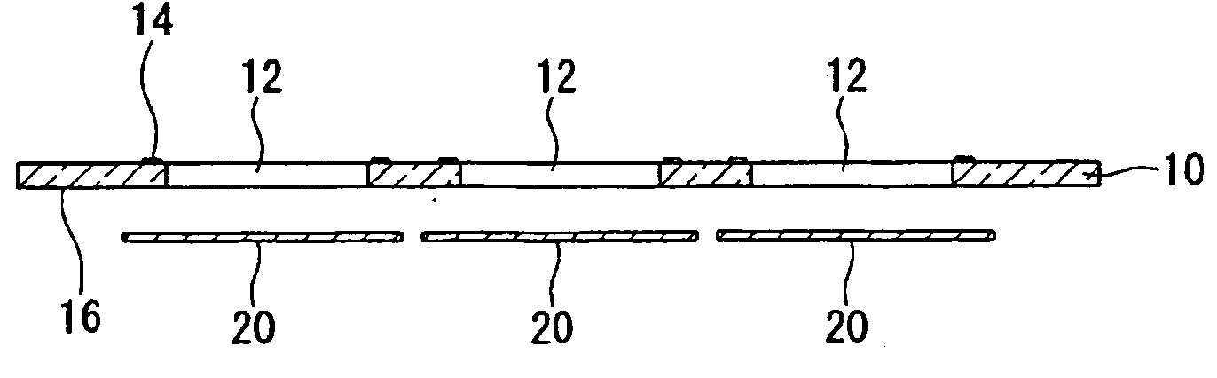
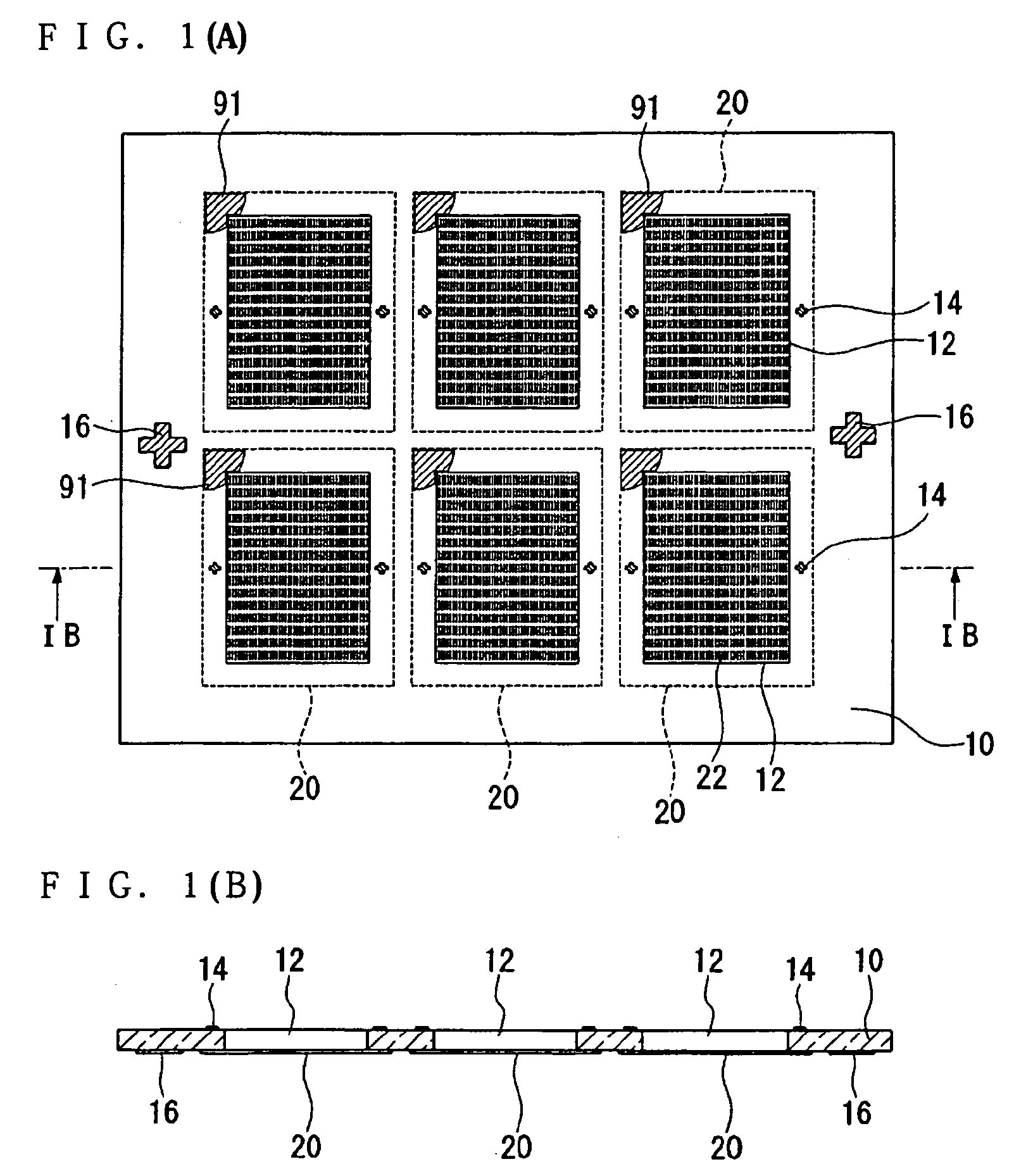
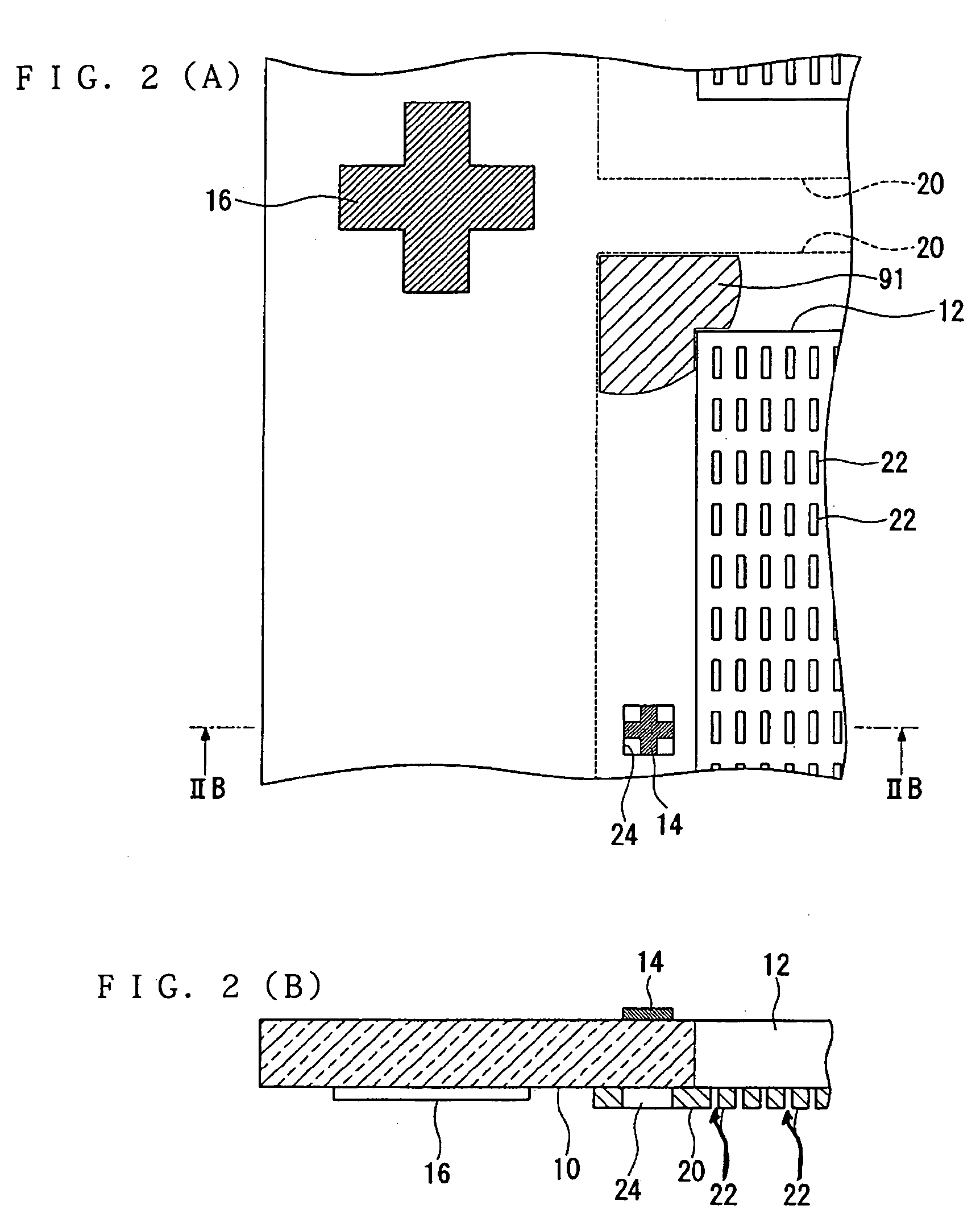
[0031]FIG. 1(A) is a flat pattern view of the mask according to an embodiment of the present invention, and FIG. 1(B) is a cross sectional view taken on a IB-IB line of FIG. 1(A). FIG. 2(A) is a flat pattern view of an enlarged principal part of the mask in accordance with the embodiment of the present invention, and FIG. 2(B) is a cross sectional view taken on a IIB-IIB line of FIG. 2(A). The mask of the present embodiment is composed of a first substrate 10 and at least one (in FIG. 1(A), a plurality of) second substrate 20. FIG. 3 is a flat pattern view showing a general structure of the first substrate 10, and FIG. 4 is a flat pattern view showing a general structure of the second substrate 20.

[0032] The first substrate 10 may be composed of a transparent substrate such as a glass substrate. On the first substrate 10, at least one (in FIG. 1(A), a plurality o...


PUM

PropertyMeasurementUnit
heightaaaaaaaaaa
adhesiveaaaaaaaaaa
luminescentaaaaaaaaaa

Abstract

A mask is provided for forming a desired high-precision layer pattern on a glass substrate or the like used as a layer-formation object material. The mask includes a first substrate having a first aperture and a second substrate having a plurality of second apertures serving as mask apertures, wherein the second apertures are placed inboard of the first aperture and the second substrate is partially bonded to the first substrate.

Description

RELATED APPLICATIONS [0001] This application claims priority to Japanese Patent Application No. 2003-403070 filed Dec. 2, 2003 which is hereby expressly incorporated by reference herein in its entirety. BACKGROUND [0002] 1. Field of the Invention [0003] The present invention relates to a mask, a method for manufacturing a mask, and a method for manufacturing an organic electroluminescent device (EL) and an organic EL device. [0004] 2. Related Art [0005] As a method for manufacturing a low-molecular full-color organic EL panel, there is a method in which a deposition pattern is selectively formed through a mask so as to separately color each red, blue, and green luminescent layer on a glass substrate. For example, when a metal mask is used as the mask, deposition is conducted in a condition where the mask is adhered to one side of the glass substrate by a permanent magnet placed on the other side of the. glass substrate. However, when a large-size panel is manufactured with a metal m...

Claims


Application Information

Patent Timeline
Patent Type & Authority Applications(United States)
IPC IPC(8): C23C14/04H01L51/50H05B33/10
CPCH05B33/10H10K71/166
Inventor KUWAHARA, TAKAYUKIYOTSUYA, SHINICHI
Owner SEIKO EPSON CORP
Why Eureka
Try Eureka