DC offset cancellation in a wireless receiver

a wireless receiver and dc offset technology, applied in the field of dc offset cancellation in the wireless receiver, can solve the problems of static dc offset, the technique cannot be applied to a system in which the receiver does not continuously operate, and the technique cannot be effectiv

Active Publication Date: 2005-06-02
SKYWORKS SOLUTIONS INC
View PDF15 Cites 21 Cited by
  • Summary
  • Abstract
  • Description
  • Claims
  • Application Information

AI Technical Summary

Problems solved by technology

The DC offset occurs due to filter mismatch and also due to self-mixing that can occur with the local oscillator (LO) signal, the radio frequency (RF) signal or interfering signals in the receiver.
Typically, filter mismatch due to temperature change over time results in static DC offset.
Unfortunately, one or all of these techniques can only be applied to a system in which the receiver does not continuously operate, such as in a TDMA communication system.
In a CDMA system, these techniques will not be effective because the receiver works continuously with no interruption.
Furthermore, DC-offset correction using so called “auto-zeroing” techniques during start-up is not practical in a CDMA system because of dynamic offsets.
Unfortunately, in a servo-loop architecture, the high pass cut-off frequency is dependent upon the gain characteristics of the variable gain amplifier and the amplifiers in the servo-loop.
Unfortunately, such a servo-loop increases significantly the complexity, power consumption and the area on the device occupied by the architecture.

Method used


Image

  • DC offset cancellation in a wireless receiver
  • DC offset cancellation in a wireless receiver
  • DC offset cancellation in a wireless receiver

Examples


Embodiment Construction

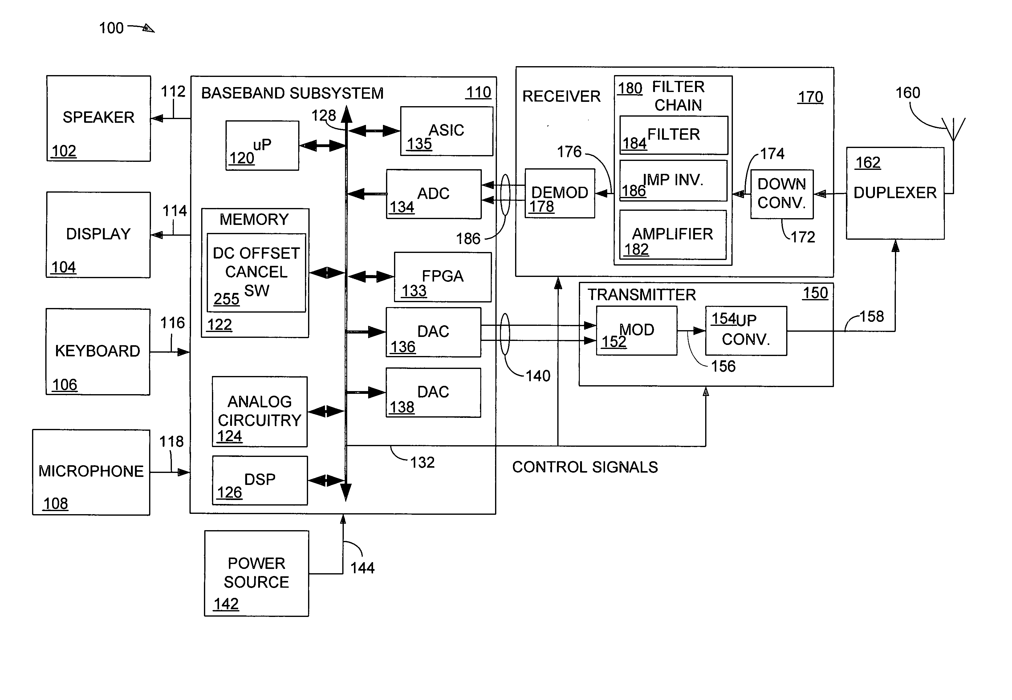
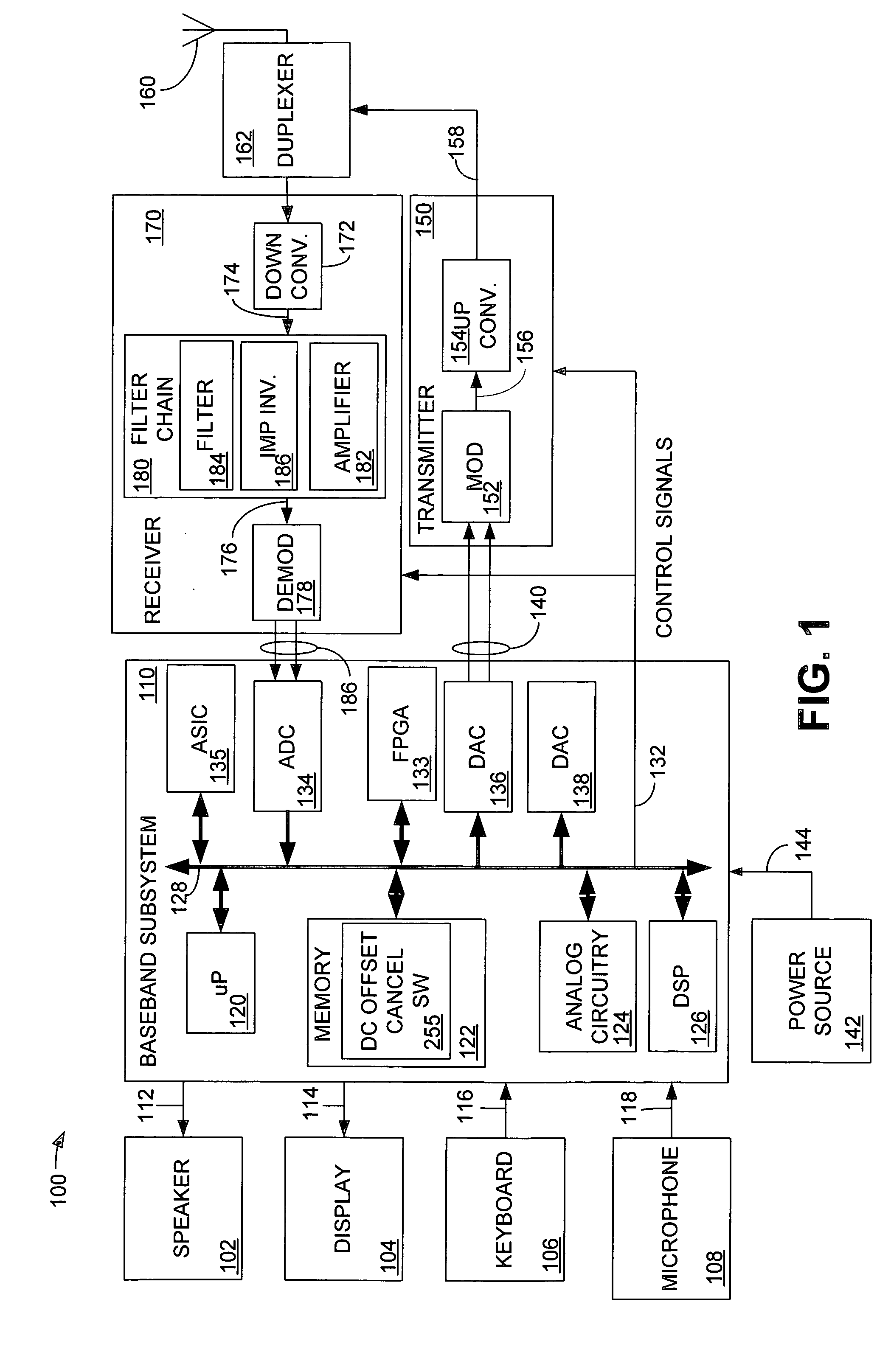
[0020] Although described with particular reference to a portable transceiver, the DC-offset cancellation system can be implemented in any communication device employing a direct conversion receiver and in which the receiver operates continuously.

[0021] The DC-offset cancellation system can be implemented in hardware, software, or a combination of hardware and software. When implemented in hardware, the DC-offset cancellation system can be implemented using specialized hardware elements and logic. When the DC-offset cancellation system is implemented partially in software, the software portion can be used to control the components so that various operating aspects can be software-controlled. The software can be stored in a memory and executed by a suitable instruction execution system (e.g., a microprocessor). The hardware implementation of the DC-offset cancellation system can include any or a combination of the following technologies, which are all well known in the art: discreet...


PUM


Abstract

A DC-offset cancellation system for a wireless receiver is disclosed. The DC-offset cancellation system comprises an amplifier and an impedance inverter configured to transform inductance applied to a received signal to a capacitance.

Description

BACKGROUND OF THE INVENTION [0001] 1. Field of the Invention [0002] This invention relates generally to receiver circuit architecture in a wireless portable communication device. More particularly, the invention relates to DC offset cancellation in a wireless receiver. [0003] 2. Related Art [0004] With the increasing availability of efficient, low cost electronic modules, mobile communication systems are becoming more and more widespread. For example, there are many variations of communication schemes in which various frequencies, transmission schemes, modulation techniques and communication protocols are used to provide two-way voice and data communications in a handheld, telephone-like communication handset. The different modulation and transmission schemes each have advantages and disadvantages. [0005] As these mobile communication systems have been developed and deployed, many different standards, to which these systems must conform, have evolved. For example, in the United Stat...

Claims


Application Information

Patent Timeline
Patent Type & Authority Applications(United States)
IPC IPC(8): H04B1/30
CPCH04B1/30
Inventor ISMAIL, ALY M.
Owner SKYWORKS SOLUTIONS INC
Why Eureka
Try Eureka