Apparatus and method for delivery of therapeutic and/or diagnostic agents

Active Publication Date: 2005-06-02
MEDSOLVE TECH
View PDF19 Cites 51 Cited by
  • Summary
  • Abstract
  • Description
  • Claims
  • Application Information

AI Technical Summary

Benefits of technology

[0009] In a first separate aspect of the present invention, a port assembly includes a base with a cannula extending from the mounting side and a port opening away from the mounting side. A resilient barrier is located between the port and the cannula. An access hub includes a connector, a fitting and a passage extending through the fitting and the connector. The connector is positionable in the port at the resilient barrier. The resilient barrier is open with the connector positioned in the port. The connector being positionable in the port at the resilient barrier substantially eliminates the dead space that must be primed with fluid in order to achieve an accurate delivery of therapeutic agent.
[0010] In a second separate aspect of the present invention, a port assembly includes a base with a cannula extending from the mounting side and a port opening away from the mounting side. A valve is located between the port and the cannula. The valve includes a resilient body with a slit therethrough. The slit is closed when unstressed. An access hub includes a connector, a fitting and a passageway extending through the fitting and the connector. The connector is positionable at the port. The valve is open with the connector engaging the valve at the port. The access hub can be positioned and replaced without impacting the integrity of the valve. In addition, the connector need not extend through the valve. Pr

Problems solved by technology

Some medical procedures employ the infusion of therapeutic agents into living bodies over periods of time, making a syringe inconvenient and/or inappropriate.
In other cases, monitoring of internal body conditions with small sensors or other devices also makes syringes and

Method used


Image

  • Apparatus and method for delivery of therapeutic and/or diagnostic agents
  • Apparatus and method for delivery of therapeutic and/or diagnostic agents
  • Apparatus and method for delivery of therapeutic and/or diagnostic agents

Examples


Embodiment Construction

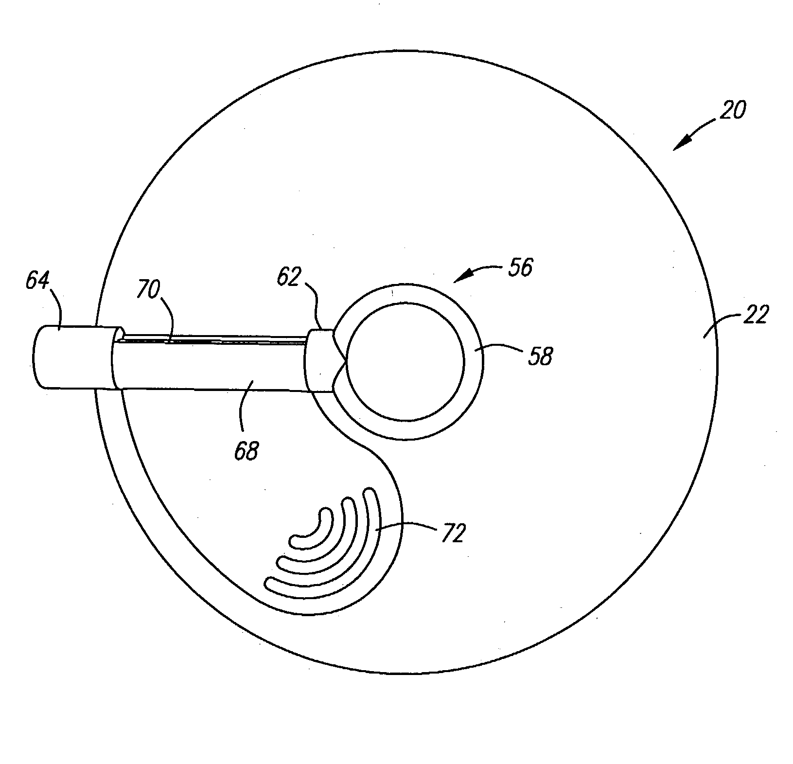
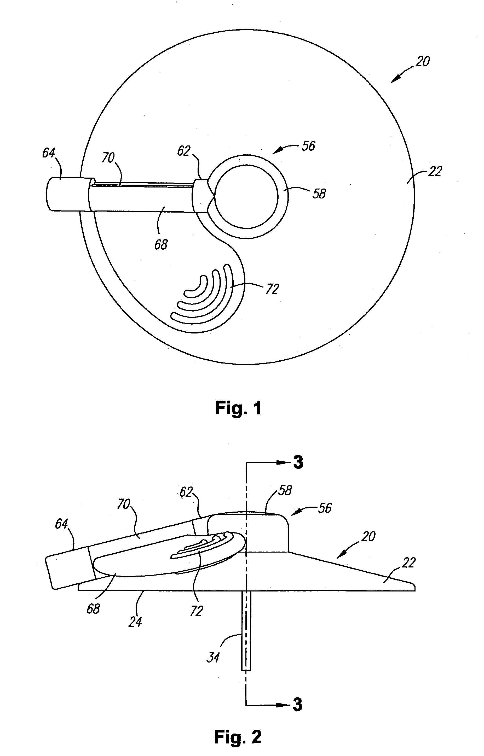
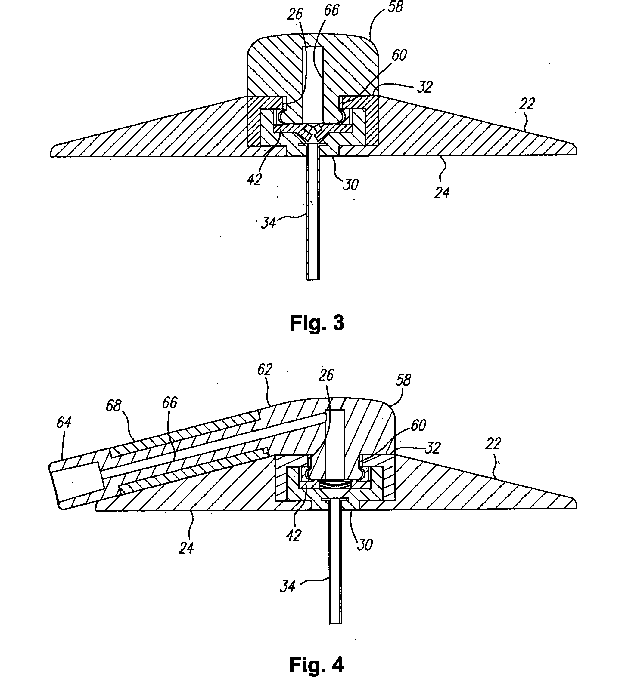
[0040] Turning in detail to the drawings, FIGS. 1 through 7 illustrate a first port assembly, generally designated 20. The port assembly 20 includes a base 22 which is shown to be frustoconical. The base may alternatively be cylindrical. Other shapes, of course, can also be employed. The base includes a mounting side 24. The mounting side may include adhesive for retention at a site on a living body. The adhesive is preferably nondrying and may or may not include a coated paper cover to be removed prior to use. A port 26 is arranged in the base 22 to be open to the other side of the base from the mounting side 24. In this embodiment, the port opens into a cavity 28 defined by a cannula mounting element 30 and a retainer element 32 which are sonically welded, press fit or cemented into the main part of the base 22.

[0041] A cannula 34 extends from the base 22. In this embodiment, the cannula extends perpendicular to the mounting side 24. Other angles might be appropriately employed. ...


PUM


Abstract

A system for delivery of therapeutic and/or diagnostic agents into a living body includes a port assembly having a cannula extending from the mounting side, a port opening away from the mounting side and a resilient barrier between the port and the cannula. An access hub includes a connector positionable at the port for opening the resilient barrier. The access hub is movable in the port assembly, is engaged therewith through a resilient ring coupling and forms a seal with the resilient barrier, reducing the amount of volume to be primed. Inserters, both disposable and reusable, include the cannula insertion member as part of the assembly. A spring loaded port driver is operatively mounted within the housing with movement controlled by a latch. The driver includes a seat for receipt of a port assembly. The cannula insertion member is nonremovably fixed in a socket in the port driver in the disposable assembly. In the reusable inserter, the cannula insertion member is slidably mounted within a socket associated with the latch. Slidable movement is limited by locking shoulders. The socket is split and may be splayed to release the cannula insertion member following use.

Description

BACKGROUND OF THE INVENTION [0001] The field of the present invention is devices and methods for the delivery or placement of therapeutic or diagnostic agents into a living body. [0002] Some medical procedures employ the infusion of therapeutic agents into living bodies over periods of time, making a syringe inconvenient and / or inappropriate. Such procedures have been used for the infusion of insulin, for example. In other cases, monitoring of internal body conditions with small sensors or other devices also makes syringes and like devices inappropriate for continuing access to subcutaneous tissue. To provide access in either circumstance, ports have been devised which provide support for a flexible cannula implanted in the body. Ports typically provide a housing which has a mounting side that is held by tape, dressings or direct adhesive against the body. A flexible cannula extends from the housing into the body. [0003] Ports used for infusion may be employed in combination with a ...

Claims


Application Information

Patent Timeline
IPC IPC(8): A61M5/158A61M5/178A61M5/20A61M25/00A61M25/16A61M25/18A61M31/00A61M39/04A61M39/26A61PA61P1/00
CPCA61M5/158A61M39/04A61M39/26A61M2205/8281A61M2005/1585A61M2005/1587A61M2005/1581A61P1/00
Inventor MARANO-FORD, APRILMCCONNELL-MONTALVO, SUSANFIELD, JEFFREY F.
Owner MEDSOLVE TECH
Why Eureka
Try Eureka