
Therapeutic Delivery Device

a delivery device and tissue technology, applied in the field of therapeutic delivery devices, can solve the problems of limiting the repair process, limiting the ability of the disc to be repaired by a therapeutic, and difficult to reach within the patient's body, so as to minimize the damage to the environment, accurate delivery of therapeutics, and the effect of reducing the invasiveness

Active Publication Date: 2011-11-10
REGENEXX LLC
View PDF7 Cites 85 Cited by
  • Summary
  • Abstract
  • Description
  • Claims
  • Application Information

AI Technical Summary

Benefits of technology

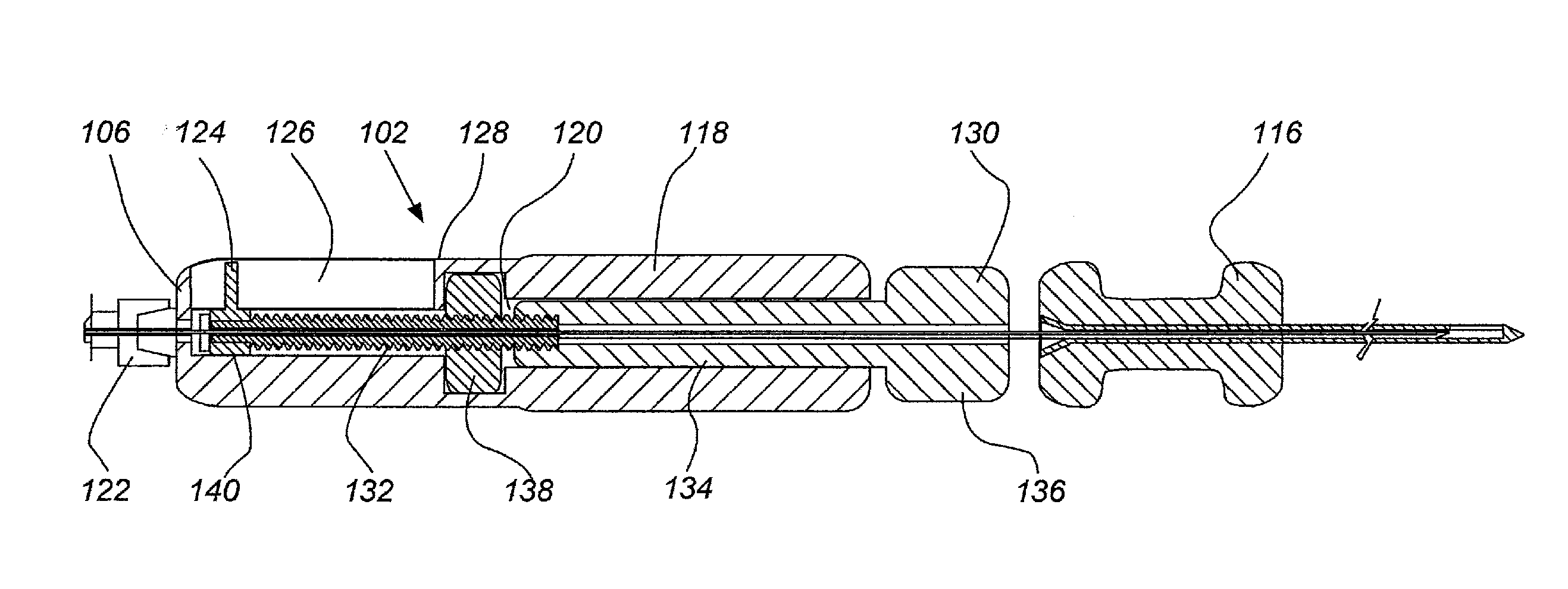
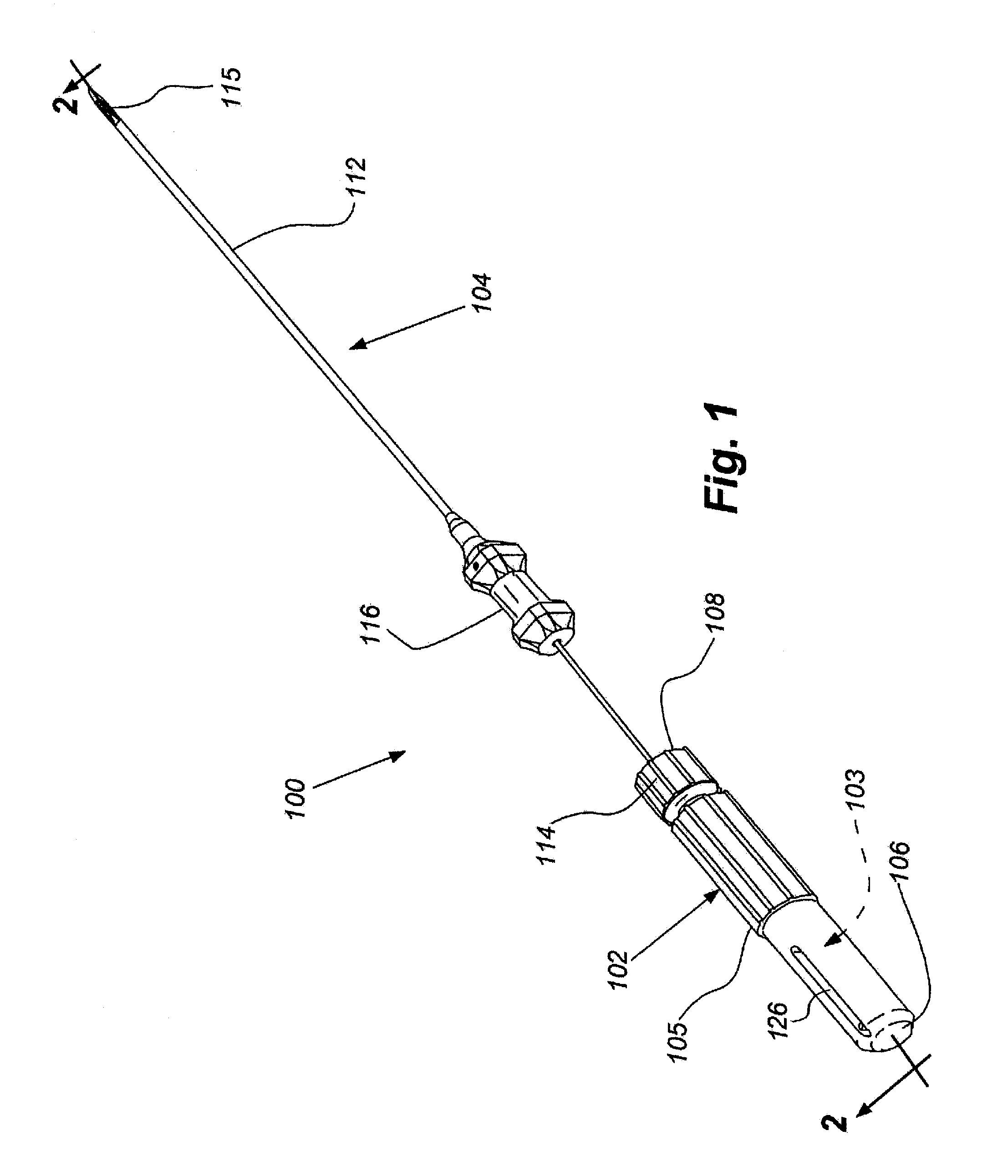
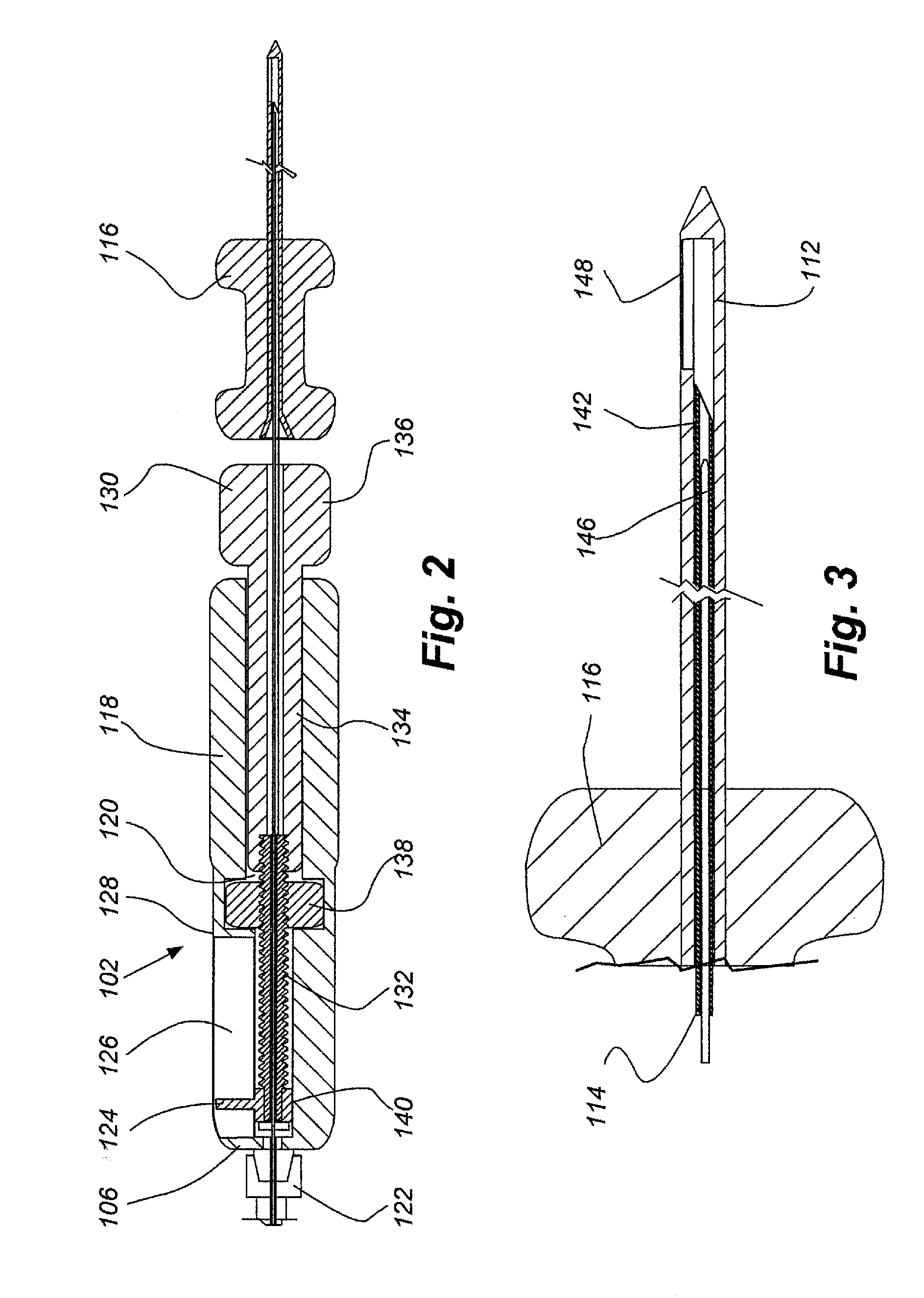
[0014]In one embodiment, a therapeutic delivery device, or delivery device, is provided that includes a needle assembly. The needle assembly can include either: 1) an introducer needle that internally constrains an advanceable cannula or 2) an introducer needle having the advanceable cannula and further includes an advanceable catheter internally constrained within the cannula. Aspects of the needle assembly allow the cannula and catheter to be independently advanced by a user from the introducer needed to exact distances and with exact arch. The ability to advance the cannula and catheter to specific distances and arches allows for minimal invasiveness of and within the environment of the target site by the delivery device. Needle assembly embodiments herein allow for accurate delivery of therapeutics to target sites in the patient by minimizing damage to the environment around the target site. Aspects of the needle assembly have also been optimized to minimize damage to the therapeutic during the delivery process, for example, minimize damage to stem cells while moving through the delivery device to the target site ensuring high viability of the delivered cells. The catheter and cannula can be produced from memory metal alloys, for example, Nitinol. The introducer needle and cannula can include an alignment marker to ensure proper alignment between the two and provide the user with additional information on positioning of cannula during use.
[0015]In another embodiment, a delivery device is provided that includes a handle assembly and a needle assembly. In typical embodiments the handle assembly and needle assembly cooperate to house and deliver the introducer needle, cannula and potentially the catheter to a target site in a patient in need thereof. The arch and distance that the cannula extends from the introducer needle occurs as the cannula is extended out of a pre-positioned introducer needle. As described above, a catheter can be constrained within the cannula and is further advanced out of the cannula once the cannula is positioned within the target site. The handle assembly provides grip convenience to the user during use of the needle assembly. The handle assembly can also include a controller for control of aspects of the needle assembly off of the handle assembly.
[0016]In one embodiment the delivery device is optimized for placement of a biologic therapeutic to a target site in a disc. Device embodiments herein are optimized for their capacity to place therapeutics at a specific site of interest in the disc, all the while allowing the health care professional to take a transpedicular approach, for example. Other embodiments of the delivery device are optimized for placement of a biologic therapeutic to a ligament or to a labrum. In some embodiments the delivery device is optimized for placement of cells, for example stem cells, e.g., mesenchymal stem cells, embryonic stem cells, very small embryonic stem cells, blastomere like stem cells, hematopoetic stem cells, annulus fibrosis cells, cord blood cells, other adult stem cells at a target site, including minimizing forces acting on cells during movement through the delivery device. Still other embodiments of the delivery device are optimized for placement of growth factors, glycoaminosglycans, fibrin, fibrin glue, or other substances meant to initiate repair of the annulus.

Problems solved by technology

Often these repair sites are difficult to reach within a patient's body or are sites in tissue where any disturbance of the surrounding environment can exacerbate and limit the repair process.
Manipulation of the disc environment, annulus or pulposus, can lead to additional damage and can further limit the capability of the disc to be repaired by a therapeutic.
Back pain often results from disruption of one or more disc in a patient's spine.
Disc disruption is typically caused by trauma, inflammation, herniation, and / or instability of adjacent vertebral bodies.
However, in some circumstances a damaged disc requires surgical intervention to facilitate repair of the damaged tissue.
However, little advancement has been made to facilitate these new therapies, especially with regard to the placement of the therapeutics in the damage site.
Little progress has been made in these stem cell or therapeutic delivery techniques.

Method used


Image

  • Therapeutic Delivery Device
  • Therapeutic Delivery Device
  • Therapeutic Delivery Device

Examples


example 1

Cadaver Testing Utilizing Several Delivery Device Embodiments

[0081]FIGS. 13, 14A and B, 15A and B, 16A and B, 17A and B and 18 provide illustrative visualization of a delivery device embodiment of the invention in use during cadaver testing. X-rays were taken of variously positioned device embodiments in accordance with the present invention. FIG. 13 shows a guide cannula fully deployed with catheter advanced to annular-nucleus interface; FIG. 14A shows a L5 / S1 Lateral, with rotation of bevel up resulting in cannula and catheter driving cephalad and FIG. 14B shows L5 / S1 Lateral, with rotation of bevel down resulting in cannula and catheter driving caudally; FIG. 15A shows L5 / S1, rotation of bevel up resulting in cannula and catheter driving cephalad and FIG. 15B shows L5 / S1, rotation of bevel down resulting in cannula and catheter driving caudally; FIG. 16A shows an end table view where the arrow points to a catheter exiting a guide cannula and FIG. 16B shows a end table view where ...

example 2

Stem Cells Viability Based on Cannula Composition and Diameter

[0082]In order to further ascertain utility of various embodiments of the delivery device, mesenchymal stem cell viability was determined before and after injection through a Nitinol guide cannula.

[0083]A guide cannula constructed from Nitinol having a 0.024 inch diameter shows little adverse effect on cell viability as cells were injected / passed through the length of the cannula. Cell viability was similar to that of cells injected / passed through a stainless steel 18 g needle (0.049 inch diameter).

[0084]In particular, cultured mesenchymal stem cells were harvested and viability verified by testing a sample via a trypan blue exclusion test. Cells were then broken into two groups for injection through either the 18 g stainless steel needle or the Nitinol guide cannula. After injection, cell viability was re-determined based on how many viable cells were present after exit from either the needle or the cannula. There were 2...

example 3

Stem Cell Viability Based on Catheter Composition and Diameter

[0086]In order to further ascertain utility of various embodiments of the delivery device, mesenchymal stem cell viability was determined before and after injection through a Nitinol catheter.

[0087]A catheter constructed from Nitinol having a 0.011 inch diameter shows little adverse effect on cell viability as cells were injected / passed through the length of the catheter. Cell viability was similar to that of cells injected / passed through a stainless steel 18 g needle (0.049 inch diameter). However, unlike cells passed through the stainless steel needle, there was some cell loss in the catheter as compared to the 18 g needle.

[0088]In particular, cultured mesenchymal stem cells were harvested and viability verified by testing a sample via a trypan blue exclusion test. Cells were then broken into two groups for injection through either the 18 g stainless steel needle or the Nitinol catheter. After injection, cell viability ...


PUM


Abstract

Methods and device are provided for delivery of biologics to an intervertebral disc. Device described herein include a needle assembly and handle assembly that optimize biologic delivery parameters to a target location within a disc. The needle assembly includes the capability of advancing into the disc at pre-configured pathways that allow for minimized damaged and maximized positioning of the biologic.

Description

RELATED APPLICATIONS[0001]This application is a non-provisional application of U.S. provisional application Ser. No. 61 / 258,070, entitled “Therapeutic Delivery Device”, filed Nov. 4, 2009; and U.S. provisional application Ser. No. 61 / 258,314, entitled “Therapeutic Delivery Device”, and filed Nov. 5, 2009. Each of these references is incorporated herein by reference in its entirety.FIELD OF THE INVENTION[0002]The invention generally relates to devices and methods for treatment of damaged tissue, and more particularly, to devices and methods for delivery of therapeutics to specific sites within a damaged tissue, for example, delivery of stem cells to a site within an intervertebral disc.BACKGROUND OF THE INVENTION[0003]There are particular tissue repair procedures that require the delivery of therapeutics to a target site in a patient's body. Optimally, these repair procedures are performed in a way to minimize damage caused by the repair procedure itself while maximizing the accuracy...

Claims


Application Information

Patent Timeline
Patent Type & Authority Applications(United States)
IPC IPC(8): A61B17/34
CPCA61B17/3415A61M2025/0096A61M25/01A61B17/3472A61B17/3478A61B2017/00331
Inventor SCHULTZ, JOHN RICHARDCENTENO, CHRISTOPHER J.
Owner REGENEXX LLC
Learn More