Storage system, storage control device, and data relay method using storage control device

Active Publication Date: 2005-06-02
GOOGLE LLC
View PDF7 Cites 22 Cited by
  • Summary
  • Abstract
  • Description
  • Claims
  • Application Information

AI Technical Summary

Benefits of technology

[0020] The second storage control unit realizes two functions. One is a remote copy relay function. The remote copy relay function is a function of transmitting the entire data where the copy source volume of the first storage control device is stored, or part thereof, to the third storage control device via the second storage control device. Another f

Problems solved by technology

Conversely, when the local system and remote system are at a large distance from each other, the synchronous remote copying is generally unsuitable because of the problems associated with response delay and propagation delay.
However, in the case of an asynchronous remote copying, data transfer to the remote system has not yet been conducted when the write completion report is sent to the host computer.
Therefore, though the write completion report has been sent, it cannot be guaranteed that the storage contents of the primary volume and the storage contents of the auxiliary volume are matched.
This is because the s

Method used


Image

  • Storage system, storage control device, and data relay method using storage control device
  • Storage system, storage control device, and data relay method using storage control device
  • Storage system, storage control device, and data relay method using storage control device

Examples


first embodiment

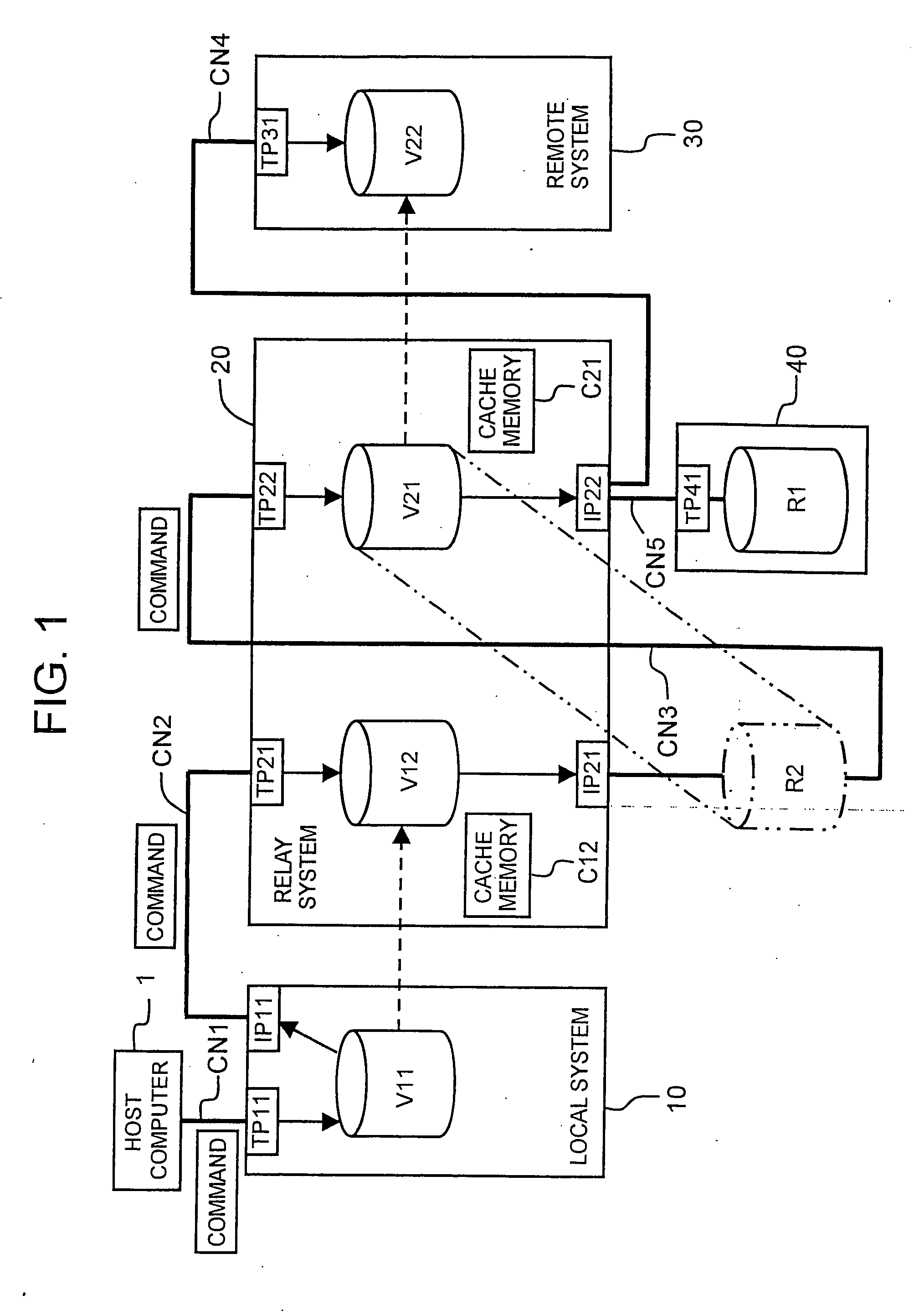
[0056] The first embodiment will be described below based on FIGS. 1 through 6. FIG. 1 is a block diagram illustrating the outline of the storage system. The present storage system, as will be described hereinbelow, comprises a host computer 1, a local system 10 serving as a first storage control device, a relay system 20 serving as a second storage control device, a remote system 30 serving as a third storage control device, and another storage control device 40.

[0057] The host computer 1 is a computer device comprising information processing resources such as a CPU (Central Processing Unit) or a memory, and is constituted, for example, by a personal computer, a workstation, a server, a mainframe, or the like. The host computer 1 comprises an information input device (not shown in the figures) such as a keyboard switch, a pointing device, a microphone, or the like, and an information output device (not shown in the figures) such as a monitor display, a speaker, or the like. Furthe...

second embodiment

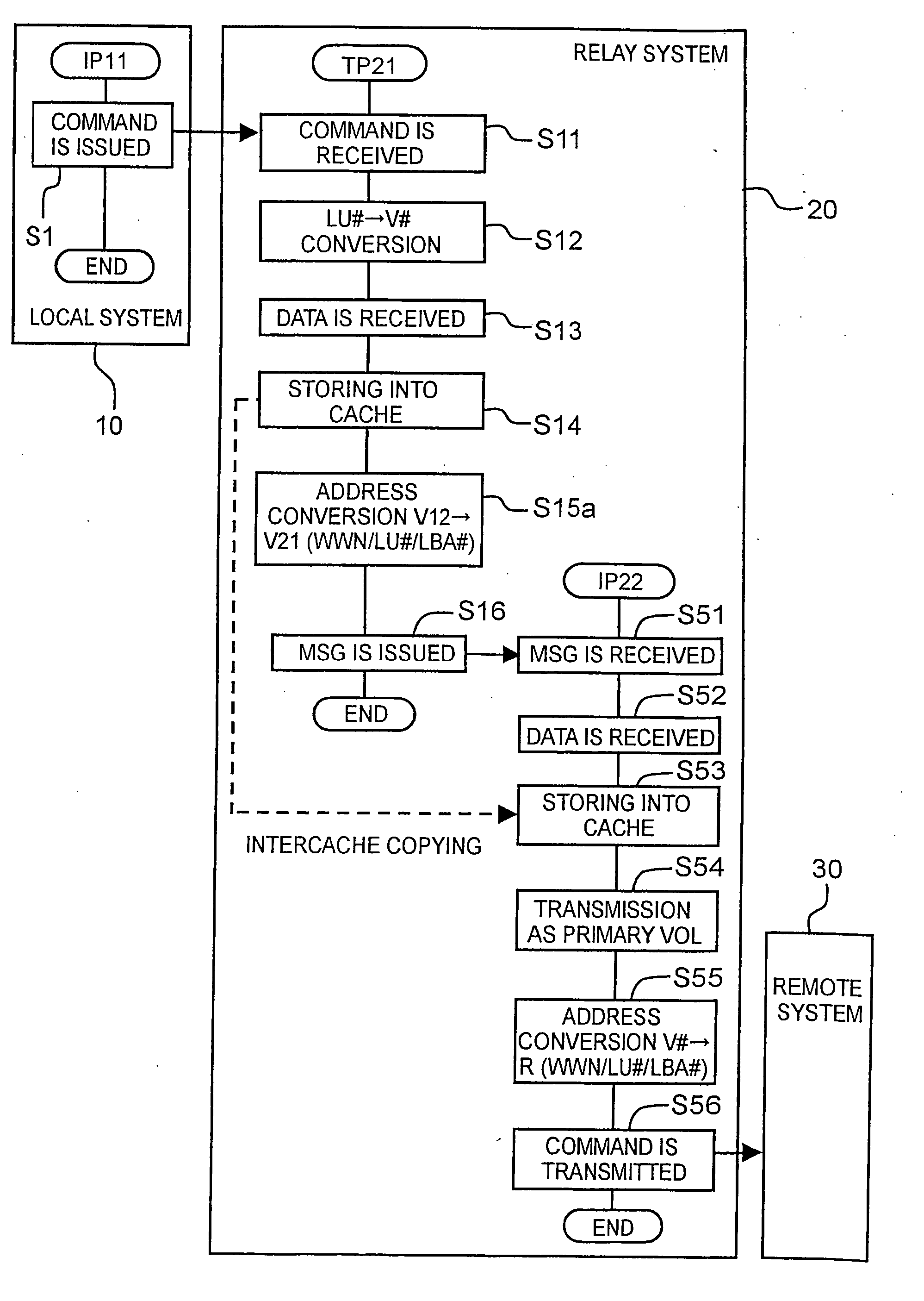
[0101] The second embodiment will be explained with reference to FIG. 7 and FIG. 8. This embodiment is equivalent to a modification example of the first embodiment. A specific feature of this embodiment is that data transfer from the first virtual volume V12 to the second virtual volume V21 is realized by interchache copying.

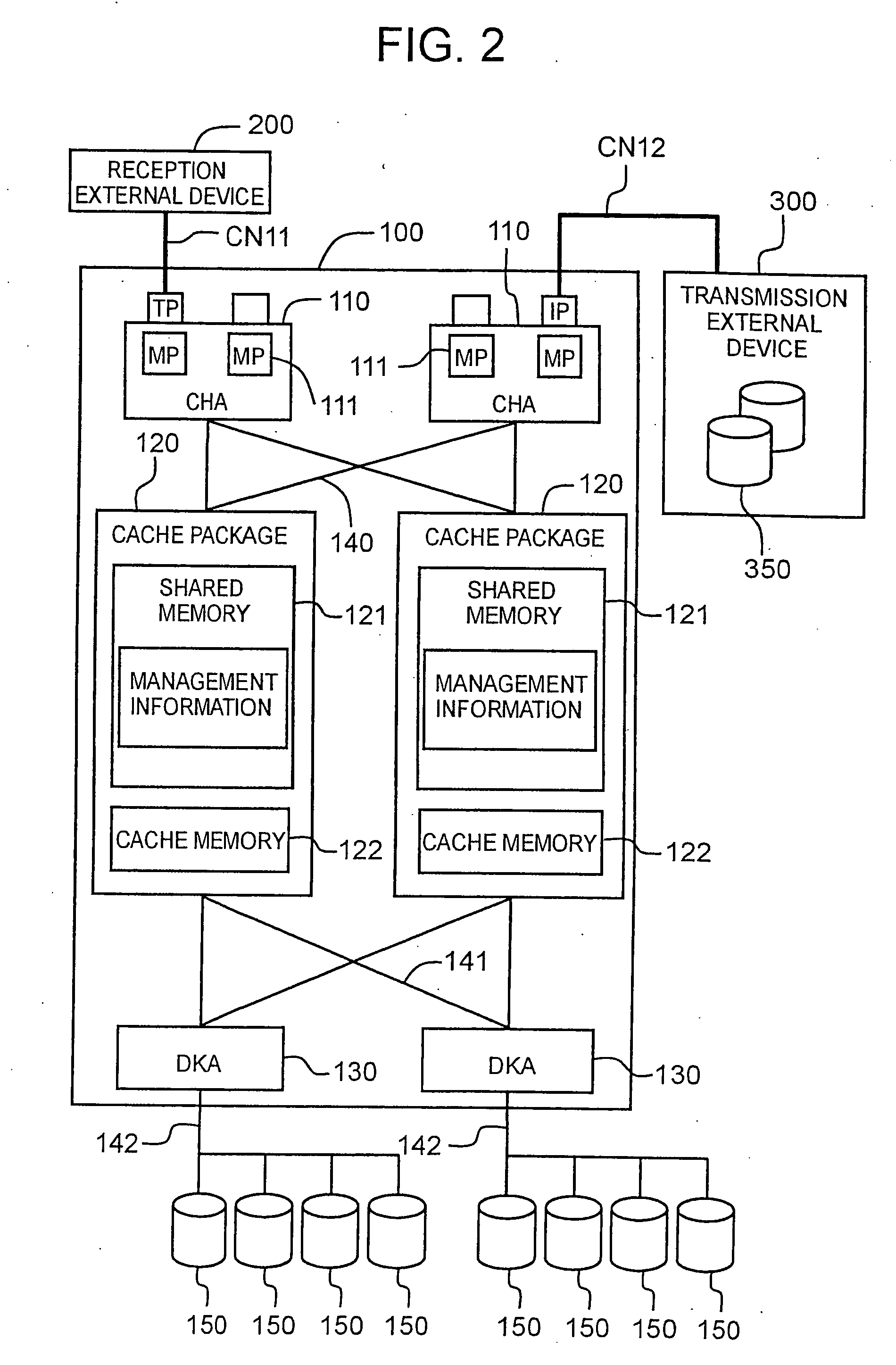
[0102]FIG. 7 is a block diagram illustrating the outline of the storage system of the present embodiment. In the present embodiment, the communication network CN3 for connecting the IP21 and TP22 is not provided. A link between the virtual volumes V12, V21 is realized by communication using a shared memory or local memory. Thus, communication between the volumes V12, V21 is conducted via the shared memory 121 shown in FIG. 2 or a local memory present in each CHA110. Therefore, in the present embodiment, a cable for connecting the IP21 and TP22 becomes unnecessary and the mechanical structure can be simplified.

[0103]FIG. 8 is a flow chart illustrating the outli...

third embodiment

[0106] The third embodiment will be explained hereinbelow based on FIG. 9 and FIG. 10. This embodiment corresponds to the second modification example of the first embodiment. A specific feature of the present embodiment, as compared to the second embodiment is that a single cache memory C21 can be shared for use between a plurality of virtual volumes V12, V21.

[0107]FIG. 9 is a block diagram illustrating the outline of the storage system of the present embodiment. In this embodiment, too, similarly to the second embodiment, the communication network CN3 connecting the IP21 and TP22 is not provided. A link between the virtual volumes V12, V21 is realized by communication using a shared memory or local memory. Furthermore, in the present embodiment, only the cache memory C21 is provided. Therefore, in the present embodiment, a cable connecting the IP21 and TP22 is not required and half of the cache memory will suffice. Therefore, the mechanical structure can be further simplified.

[01...


PUM


Abstract

A plurality of virtual volumes with different control functions are associated with one real volume and remote copying is conducted. A relay system comprises a plurality of virtual volumes V12, V21 mapped to the same real volume R1. A virtual volume V21 for transmission control is mapped to a real volume R1, a real volume R2 is mapped to the virtual volume V21, and the virtual volume V12 for reception control is mapped to the real volume R2. If a command is received from a local system 10, the virtual volume V12 for reception control writes data into the virtual volume V21 via the real volume R2 (virtual entity). The virtual volume V21 transmits the data to a copy destination volume V22 and writes the data into the real volume R1.

Description

CROSS REFERENCES TO RELATED APPLICATION [0001] This application relates to and claims priority from Japanese Patent Application No. 2003-397380 filed on Nov. 27, 2003, the entire disclosure of which is incorporated herein by reference. BACKGROUND OF THE INVENTION [0002] 1. Field of the Invention [0003] The present invention relates to a storage system, a storage control device, and a data relay method using the storage control device. [0004] 2. Description of the Related Art [0005] For example, in a database system handling large scale data, such as information management systems of data centers or enterprises, the data are managed by using a storage system configured separately from a host computer. This storage system is constituted, for example, by disk array devices. A disk array device is configured by arranging a multiplicity of storage devices in the form of an array and is constructed based, for example, on RAID (Redundant Array of Independent Inexpensive Disks). A storage d...

Claims


Application Information

Patent Timeline
IPC IPC(8): G06F3/06G06F12/00G06F12/08H04L29/08
CPCG06F3/0617G06F3/0623G06F3/065G06F3/0662Y10S707/99955H04L67/1095H04L67/1097Y10S707/99953G06F3/067
Inventor OZAKI, SATORUNAKAGAWA, YOSHIHITOHOMMA, HISAOURABE, KIICHIRO
Owner GOOGLE LLC
Why Eureka
Try Eureka