Systems and methods for calibrating osmolarity measuring devices

a technology of osmolarity and measuring device, which is applied in the field of osmolarity measurement, can solve the problems of cornea ulceration, corneal perforation, and severe impact on the eye, and achieve the effects of improving the accuracy of osmolarity measurement and accuracy

Inactive Publication Date: 2005-06-09
RGT UNIV OF CALIFORNIA
View PDF6 Cites 15 Cited by
  • Summary
  • Abstract
  • Description
  • Claims
  • Application Information

AI Technical Summary

Problems solved by technology

Disruption, deficiency, or absence of the tear film can severely impact the eye.
If unmanaged with artificial tear substitutes or tear film conservation therapy, these disorders can lead to intractable desiccation of the corneal epithelium, ulceration and perforation of the cornea, an increased incidence of infectious disease, and ultimately pronounced visual impairment and blindness.
However, these ex vivo measurements are often plagued by many difficulties.
Any dilution of the tear film invalidates the diagnostic ability of an osmolarity test for dry eye, and therefore make currently available ex vivo methods prohibitive in a clinical setting.
Because of the induction of reflex tearing and the large volume requirements for existing vapor pressure osmometers, they are currently impractical for determination of dry eye.
The Clifton Nanoliter Osmometer (available from Clifton Technical Physics of Hartford, N.Y., USA) has been used extensively in laboratory settings to quantify the solute concentrations of KCS patients, but the machine requires a significant amount of training to operate.
The Clifton Nanoliter Osmometer is also bulky and relatively expensive.
These characteristics seriously detract from it use as a clinical osmometer.
While it has long been known that conductivity is directly related to the ionic concentration, and hence osmolarity of solutions, placing the sensor under the eyelid for half a minute likely induced reflex tearing.
Furthermore, these electrodes were difficult to manufacture and posed increased health risks to the patient as compared to simply collecting tears with a capillary.
It should be apparent from the discussion above that current osmolarity measurement techniques are unavailable in a clinical setting and can't attain the volumes necessary for dry eye patients.
Disruption, deficiency, or absence of the tear film can severely impact the eye.

Method used


Image

  • Systems and methods for calibrating osmolarity measuring devices
  • Systems and methods for calibrating osmolarity measuring devices
  • Systems and methods for calibrating osmolarity measuring devices

Examples


Embodiment Construction

.”

BRIEF DESCRIPTION OF THE DRAWINGS

[0015] Features, aspects, and embodiments of the inventions are described in conjunction with the attached drawings, in which:

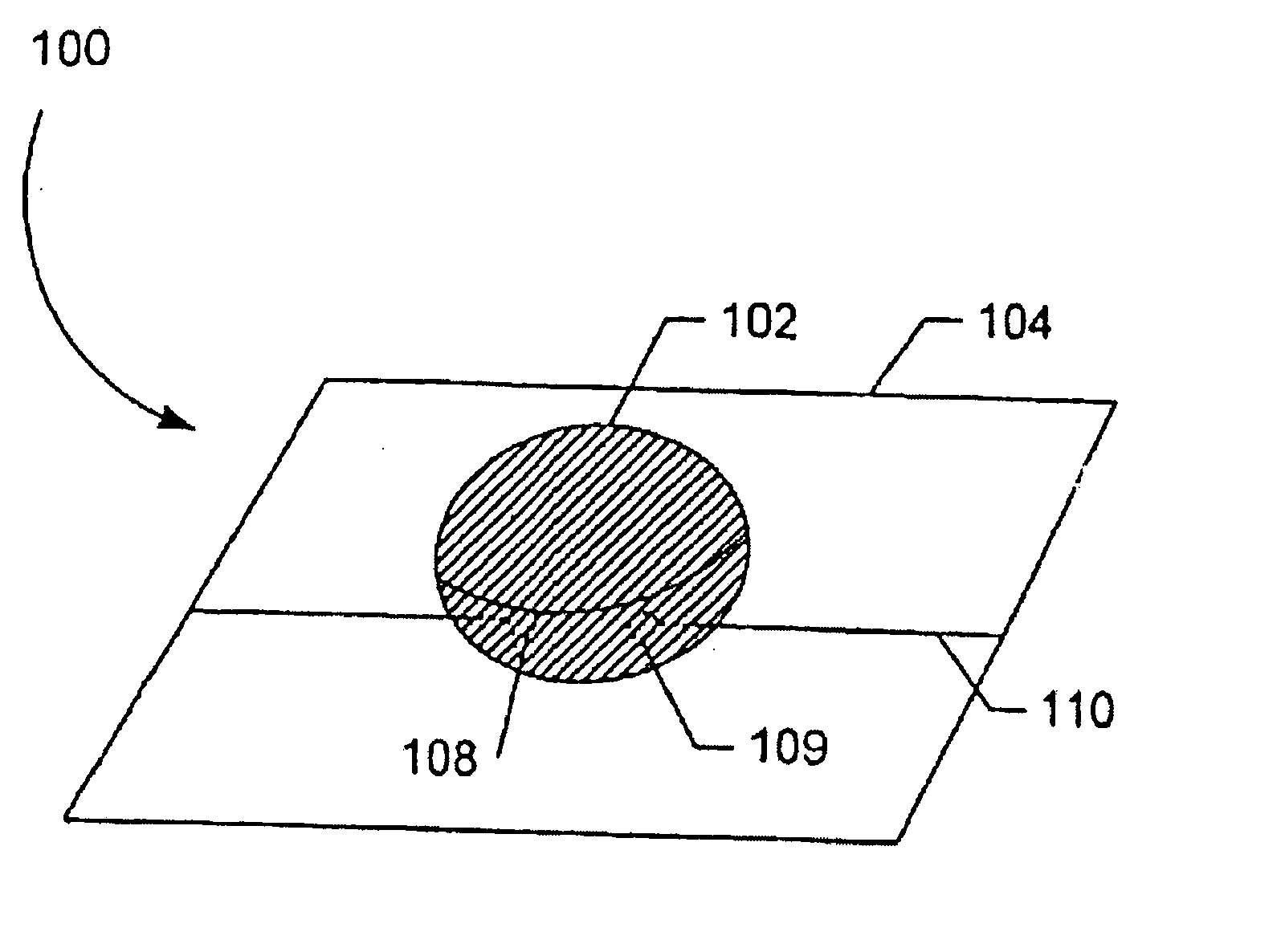
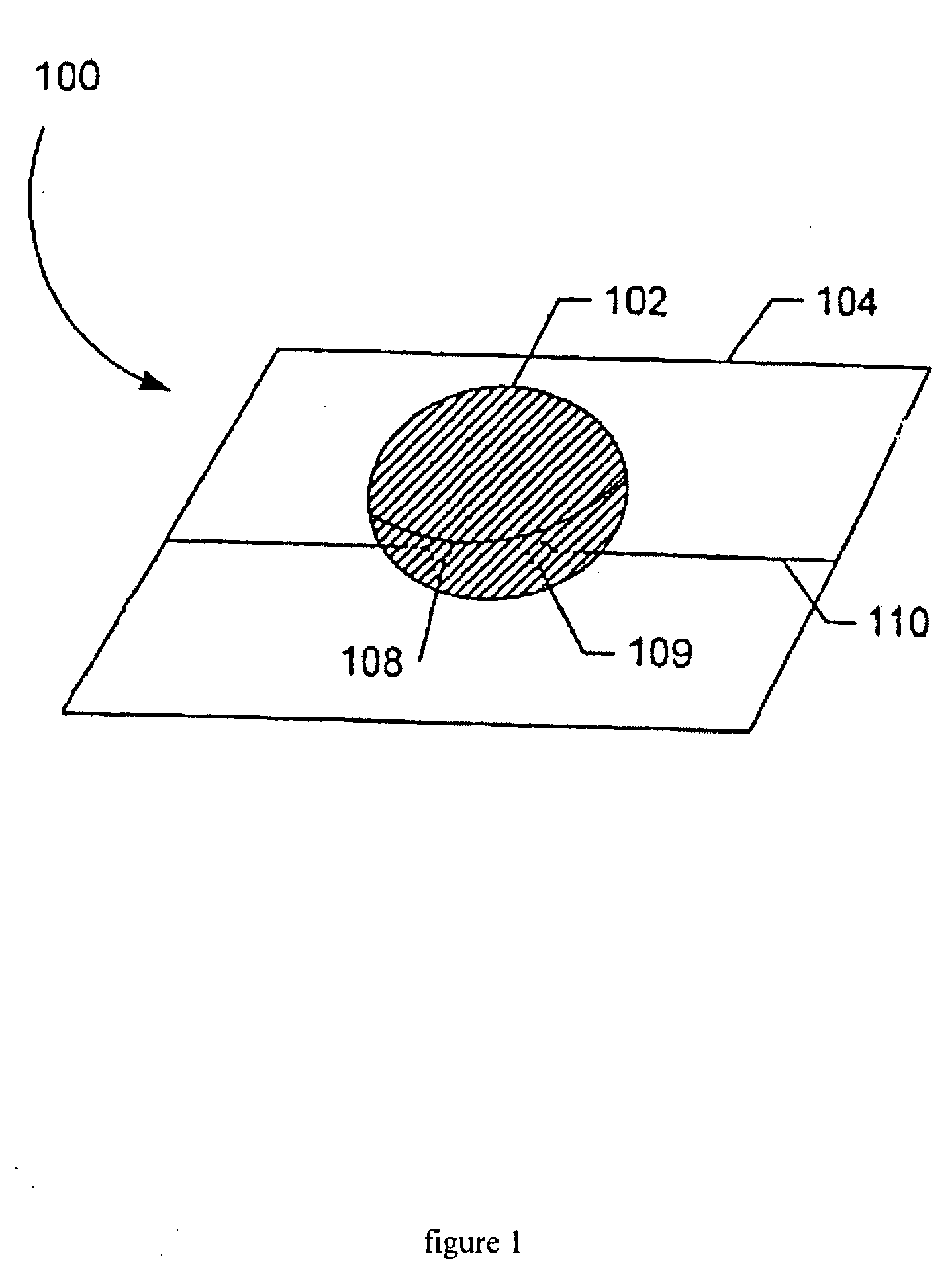
[0016]FIG. 1 illustrates an aliquot-sized sample receiving chip for measuring the osmolarity of a sample fluid;

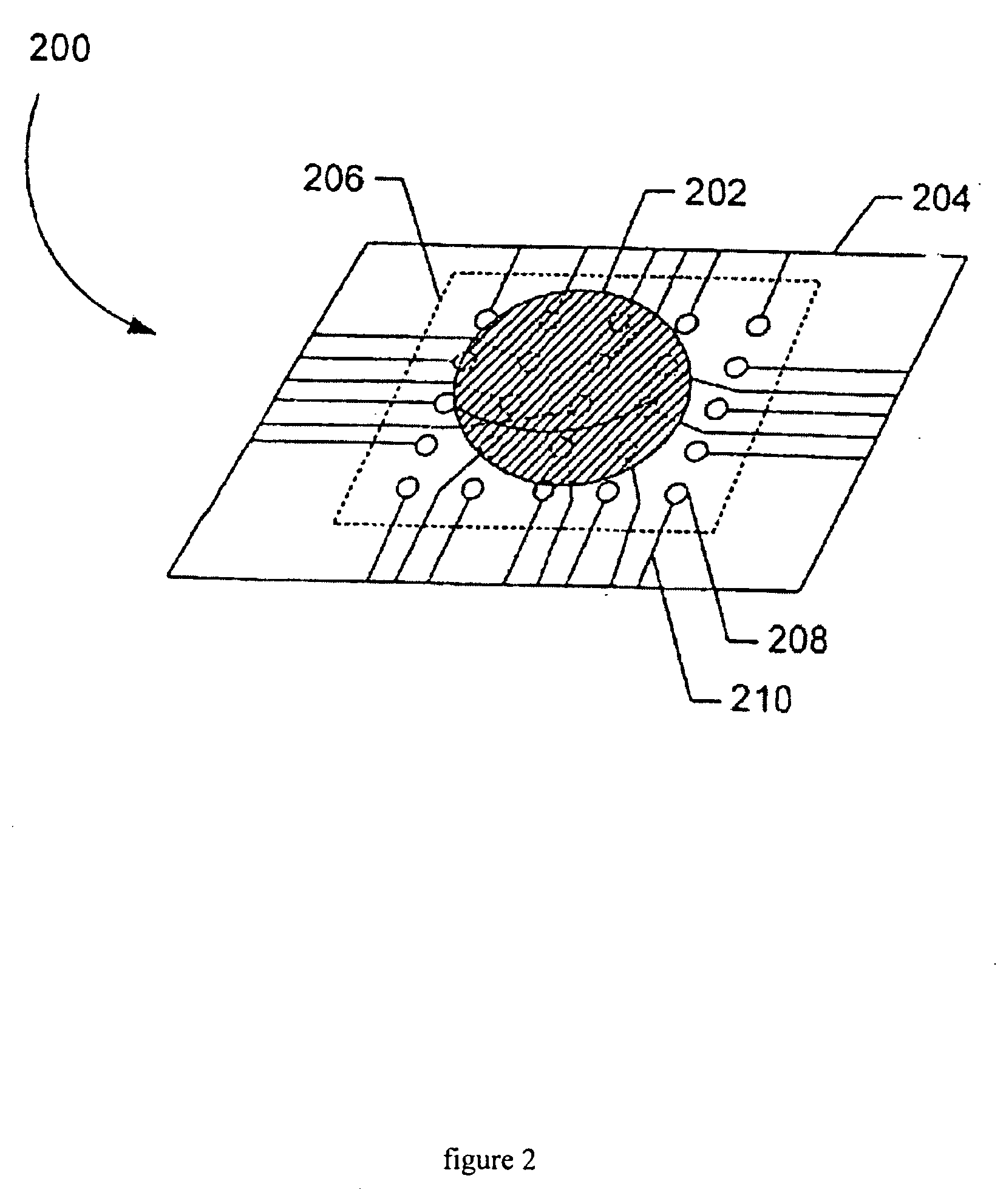
[0017]FIG. 2 illustrates an alternative embodiment of a sample receiving chip that includes a circuit region with an array of electrodes imprinted with photolithography techniques;

[0018]FIG. 3 illustrates another alternative embodiment of the FIG. 1 chip, wherein a circuit region includes printed electrodes arranged in a plurality of concentric circles;

[0019]FIG. 4 is a top view of the chip shown in FIG. 2;

[0020]FIG. 5 is a top view of the chip shown in FIG. 3;

[0021]FIG. 6 is a block diagram of an osmolarity measurement system configured in accordance with the present invention;

[0022]FIG. 7 is a perspective view of a tear film osmolarity measurement system constructed in accordance with the present invention...


PUM

PropertyMeasurementUnit
freezing pointaaaaaaaaaa
volumeaaaaaaaaaa
volumesaaaaaaaaaa

Abstract

An osmolarity measuring system comprising microscale electrode arrays is configured to account for variations and defects in the arrays using a tiered approach comprising several calibration methods. One method accounts for the intrinsic conductivity of the electrodes and subtracts out the intrinsic conductivity on a pair-wise basis, when determining osmolarity of a sample fluid. Other methods in the tiered approach use standards to determine calibration factors for the electrodes that can then be used to adjust subsequent osmolarity measurements for a sample fluid. The use of a standard can also be combined with a washing step.

Description

RELATED APPLICATIONS INFORMATION [0001] This application claims priority as a continuation-in-part to U.S. Utility Application Serial No. TBD, entitled, “Tear Film Osmometry”, filed on Mar. 25, 2002 that claims priority under 35 USC ¶119 to U.S. Provisional Patent Application Ser. No. 60 / 401,432, that was filed on Aug. 6, 2002, both of which was incorporated herein in their entirety as if set forth in full.BACKGROUND [0002] 1. Field of the Inventions [0003] The field of the invention relates generally to osmolarity measurements and more particularly to systems and methods for calibrating tear film osmolarity measuring devices. [0004] 2. Background Information [0005] Tears fulfill an essential role in maintaining ocular surface integrity, protecting against microbial challenge, and preserving visual acuity. These functions, in turn, are critically dependent upon the composition and stability of the tear film structure, which includes an underlying mucin foundation, a middle aqueous c...

Claims


Application Information

Patent Timeline
Patent Type & Authority Applications(United States)
IPC IPC(8): G01N13/04
CPCG01N13/04
Inventor SULLIVAN, BENJAMINDONSKY, ERIC
Owner RGT UNIV OF CALIFORNIA
Why Eureka
Try Eureka