Engine rotation information detection device

a technology for detecting devices and engine rotations, applied in the direction of machines/engines, electric control, instruments, etc., can solve the problems of difficult switching the recognition constant, high possibility of misidentification at the initial blast of the engine,

Active Publication Date: 2005-06-09
MAHLE INT GMBH
View PDF7 Cites 63 Cited by
  • Summary
  • Abstract
  • Description
  • Claims
  • Application Information

AI Technical Summary

Benefits of technology

[0044] As described above, the rotational direction determination means is provided to allow detection of the reverse rotation of the engine, thereby allowing safety measures to be taken for stopping an ignition operation to prevent the reverse rotation of the engine when the engine is about to rotate in reverse by an insufficient start operation force at the start of the engine.

Problems solved by technology

Thus, there is a possibility of misidentification as not the reluctor missing portion though the reluctor missing portion is passed.
When the large recognition constant α is set during the extremely low speed rotation in order to prevent misidenting the reluctor missing portion by the pulsation of the rotational speed during the low speed rotation of the engine, there tends to be a high possibility of misidentification at the initial blast of the engine.
In order to prevent this, it is supposed that the recognition constant at the initial blast of the engine is set to a small value and switched to a large value when the initial blast is completed, but the rotational speed of the engine immediately before the initial blast is a cranking speed itself and extremely unstable, and thus it is difficult to switch the recognition constant at the instant of the initial blast.
By the conventional reference crank angle position detection method, however, the reverse rotation of the engine cannot be detected as described below.

Method used


Image

  • Engine rotation information detection device
  • Engine rotation information detection device
  • Engine rotation information detection device

Examples


first embodiment

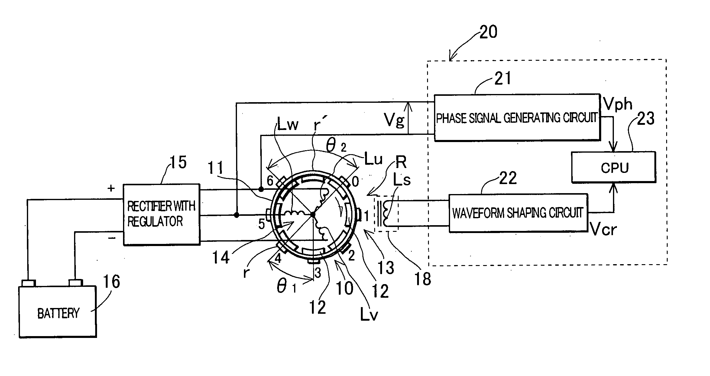
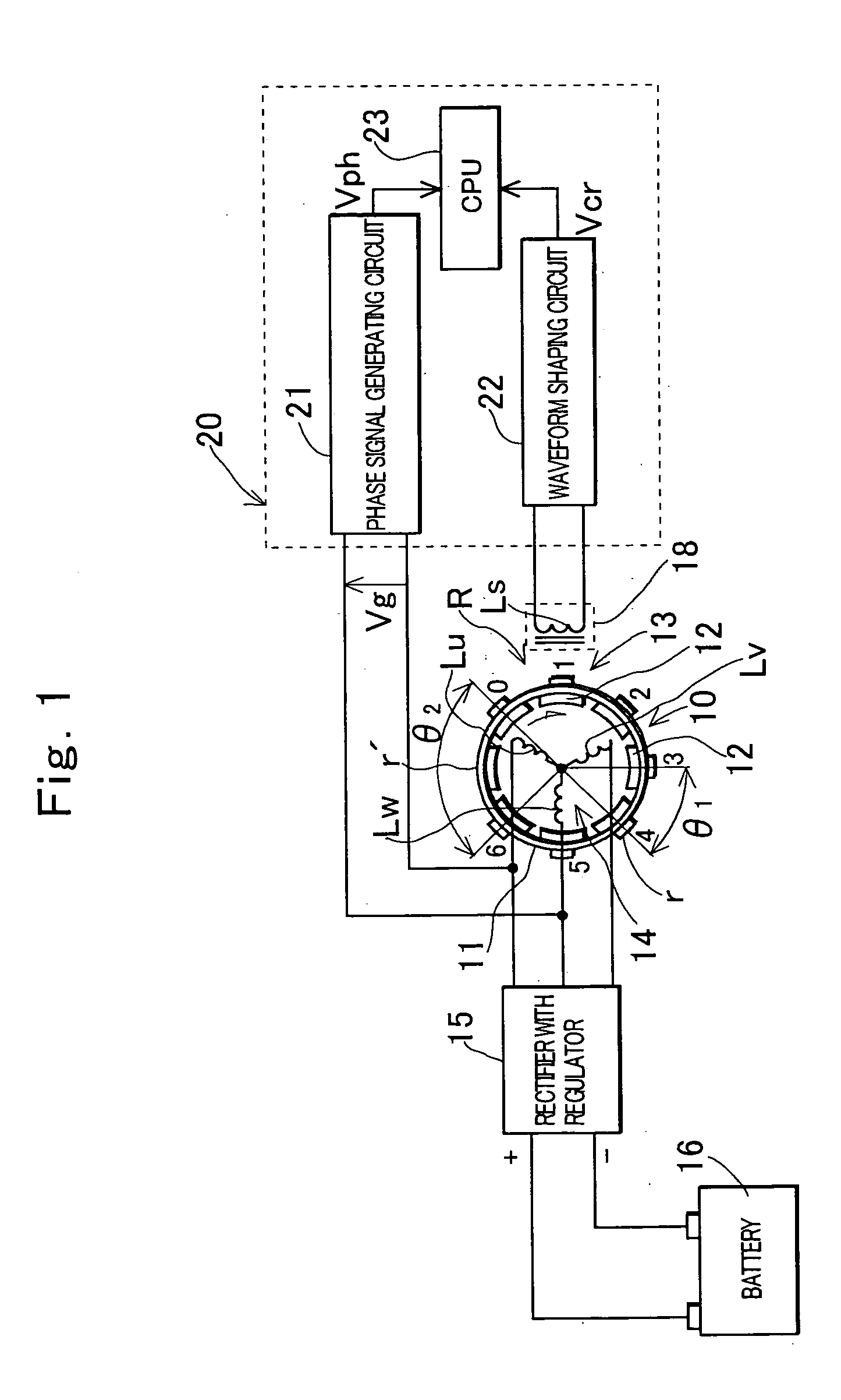
[0064]FIG. 1 schematically shows a construction of hardware of a first embodiment of the invention. In FIG. 1, 10 denotes a magneto generator having a rotor mounted to a crankshaft of an engine, and the shown generator is comprised of a magnet rotor 13 with 16 poles and a stator 14 placed inside the magnet rotor 13. The magnet rotor 13 includes a cup-shaped rotor yoke 11 mounted to the crankshaft, and permanent magnets 12 mounted to an inner periphery of a peripheral wall of the rotor yoke 11, and the magnets 12 are polarized with 16 poles to produce a magnetic field with 16 poles. The stator 14 is comprised of an armature core (not shown) with a magnetic pole portion facing magnetic poles of the magnetic field of the magnet rotor, and a three-phase armature coil Lu to Lw wound around the armature core, and secured to a stator mounting portion provided on a casing or a cover or the like of the engine. The generator 10 outputs a three-phase AC voltage from the armature coil Lu to Lw ...

second embodiment

[0085] In a second embodiment of the invention, as shown in FIG. 3, there are provided abnormality detection means 33 that detects whether an abnormality occurs in a signal system that obtains the phase signal Vph, and abnormal time reference crank angle position identification means 34 that compares lengths of detection sections θd successively appearing with rotation of a rotor to specify a detection section including a reluctor missing portion and identify a pulse generated at a reference crank angle position based on the specified detection section when the abnormality detection means 33 detects the abnormality in the signal system that obtains the phase signal. Other points are the same as the embodiment in FIG. 2.

[0086] The abnormality detection means 33 is comprised so as to determine that there is an abnormality in the signal system that obtains the phase signal Vph when no level change of the phase signal Vph is detected across the plurality of detection sections θd succes...

third embodiment

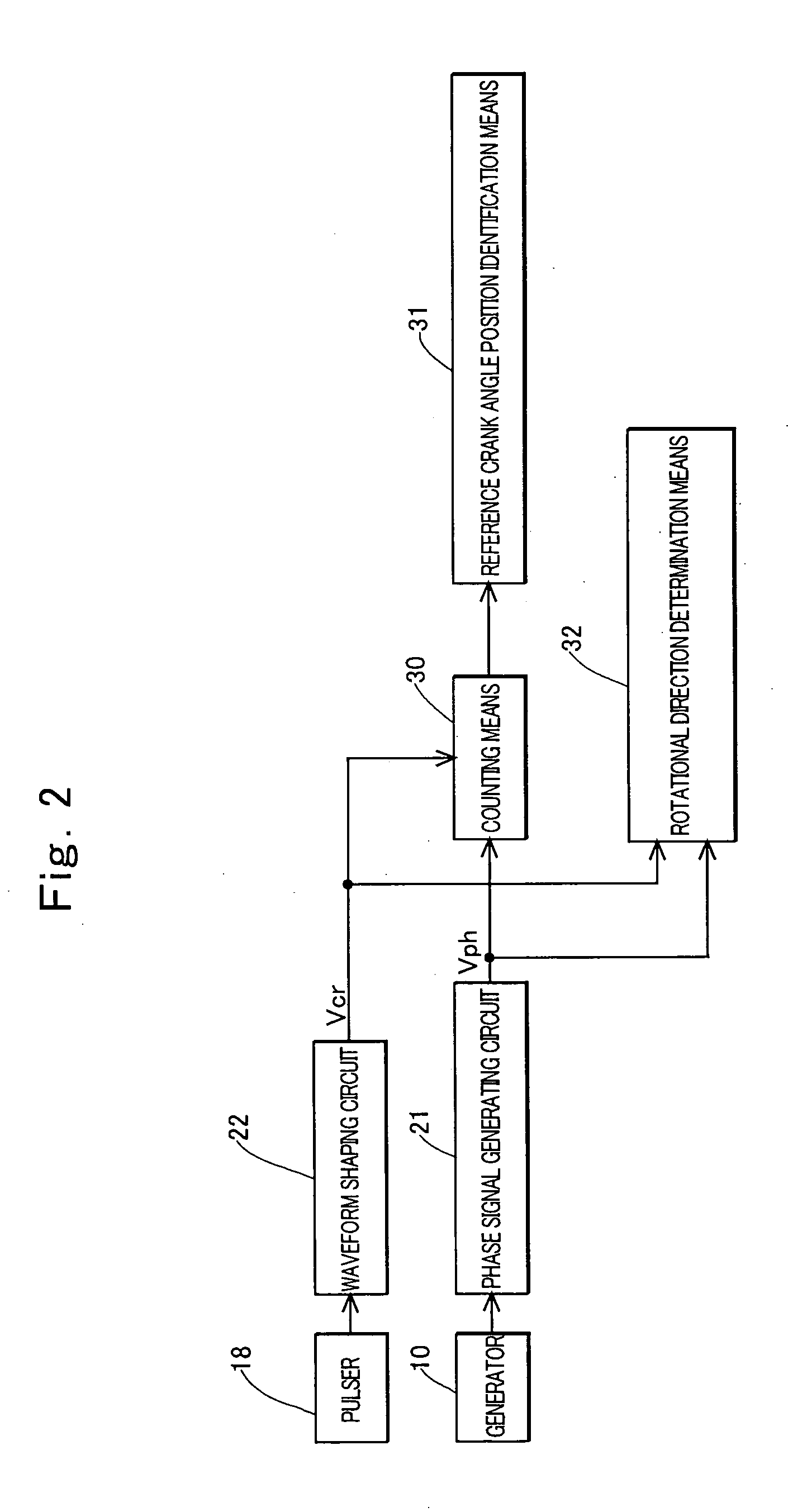
[0088] In a third embodiment of the invention, a predetermined program is executed by a CPU to construct counting means 30, start completion determination means 35, first reference crank angle position identification means 31A, second reference crank angle position identification means 31B, and rotational direction determination means 32 as shown in FIG. 4.

[0089] The counting means 30 counts the number of detections of a phase to be detected in a detection section θd, the detection section being a section between a crank angle position corresponding to any edge of each crank angle pulse generated by the waveform shaping circuit 22 and a crank angle position corresponding to any edge of a next crank angle pulse, and the phase to be detected being at least one of a phase in which the level of the phase signal Vph changes from the first level to the second level and a phase in which the level of the phase signal Vph changes from the second level to the first level.

[0090] The start co...


PUM

PropertyMeasurementUnit
crank angleaaaaaaaaaa
angleaaaaaaaaaa
AC voltageaaaaaaaaaa

Abstract

An engine rotation information detection device including: a generator that rotates in synchronization with an engine to output an AC voltage; a pulse signal generator that detects reluctors of a rotor having many reluctors and one reluctor missing portion to generate a pulse; counting means that counts the number of detections of a zero point of a waveform of the AC voltage in each detection section, the detection section being a section between a crank angle position where the pulse signal generator detects an edge of each reluctor and a crank angle position where the pulse signal generator detects a next reluctor; and reference crank angle position identification means that specifies a detection section including the reluctor missing portion from a count value counted by the counting means and identifies a pulse generated at a reference crank angle position based on the specified detection section.

Description

TECHNICAL FIELD OF THE INVENTION [0001] The present invention relates to a device for detecting rotation information including information on a reference crank angle position used for controlling an ignition position of an engine or a fuel injection time by a microcomputer. BACKGROUND OF THE INVENTION [0002] When a controlling object (such as an ignition device or a fuel injection device) included in an engine is controlled by using a microcomputer, a reference crank angle position is previously determined to detect timing for the controlling object to perform a predetermined operation with respect to the reference crank angle position. When a rotational speed of the engine needs to be obtained, a time between detection of each reference crank angle position and detection of a next reference crank angle position is measured to arithmetically operate the rotational speed of the engine from the measured time. [0003] For example, in the case where an ignition position (a crank angle po...

Claims


Application Information

Patent Timeline
Patent Type & Authority Applications(United States)
IPC IPC(8): G01D5/244F02D41/34F02D45/00F02P1/00F02P7/067G01D5/20G01D5/245G01P3/488G01P3/489
CPCF02D41/009G01D5/2013G01P3/489G01P3/488G01D5/2457
Inventor KISHIBATA, KAZUYOSHIKITAGAWA, YUICHISATO, HIROYASU
Owner MAHLE INT GMBH
Why Eureka
Try Eureka