Method and apparatus for substrate temperature control

a temperature control and substrate technology, applied in the direction of instruments, liquid/fluent solid measurement, structural/machine measurement, etc., can solve the problems of reducing the accuracy of the correlation between the flow indicated and the actual flow to both, the deviation of the process performance of the substrate to the substrate, and the effect of affecting the accuracy of the correlation between the flow and the actual flow

Inactive Publication Date: 2005-06-09
APPLIED MATERIALS INC
View PDF7 Cites 354 Cited by
  • Summary
  • Abstract
  • Description
  • Claims
  • Application Information

AI Technical Summary

Benefits of technology

[0016] A method and apparatus for gas control is provided. The method and apparatus may be used for controlling gases delivered to a chamber, controlling the chamber pressure, controlling the delivery of backside gas between a substrate and substrate support and the like. In one embodiment, an apparatus for controlling gas control includes at least a first flow sensor having a control valve, a first pressu

Problems solved by technology

In addition accelerated response to change in pressure set points is needed to reduce process cycle times. For example, gas temperature and/or pressure fluctuations upstream of the gas delivery system may make the flow through the flow sensor unstable, thereby reducing the accuracy of the correlation between the flow indicated and the actual flow to both the area between the substrate and substrate support and the restrictor.
Additionally, variation in the vacuum provided by the vacuum source may impact the flow through the restrictor, which may falsely indicate or contribute to erroneous interpretation of the amount of gas disposed between substrate and substrate support.
In critical applications, the gas available as a heat transfer medium between the substr

Method used


Image

  • Method and apparatus for substrate temperature control
  • Method and apparatus for substrate temperature control
  • Method and apparatus for substrate temperature control

Examples


Embodiment Construction

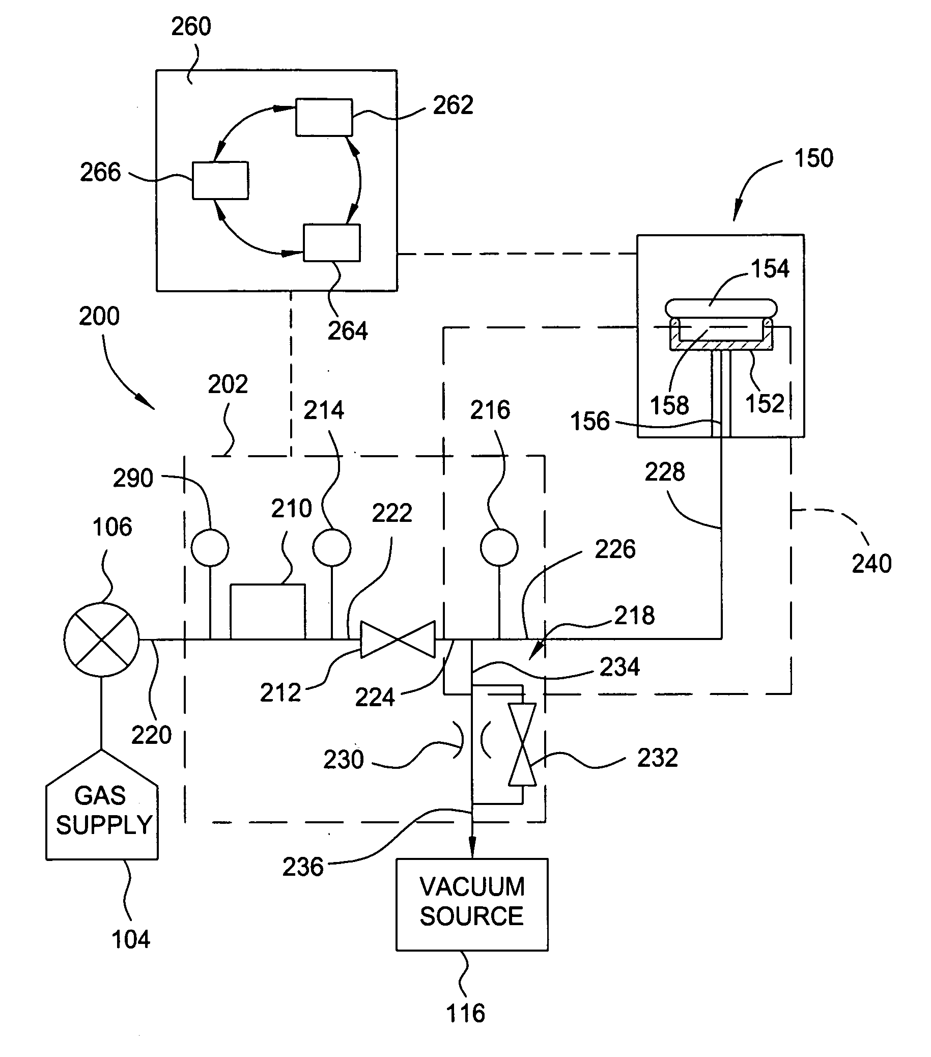
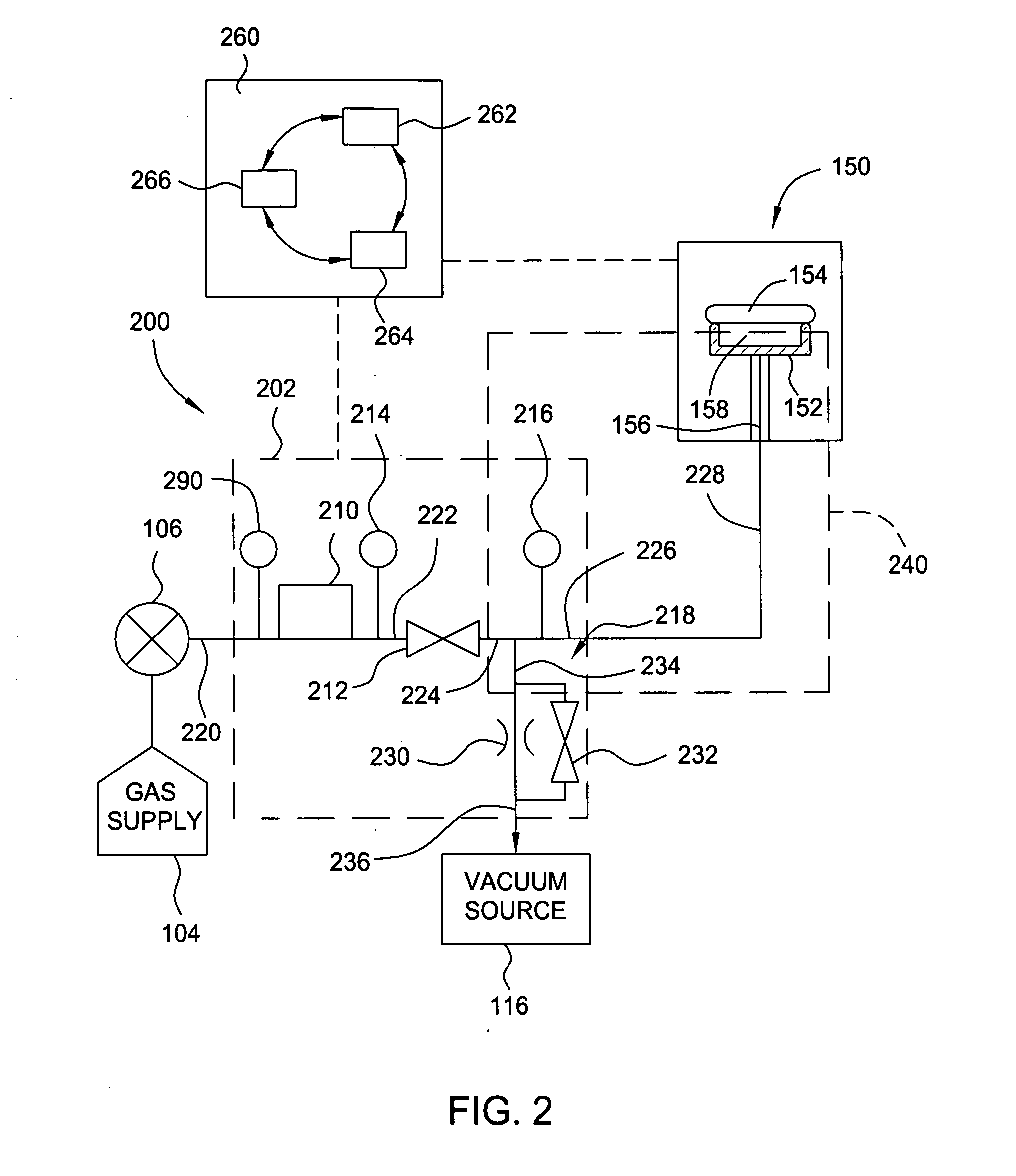
[0024]FIG. 2 depicts a simplified schematic of one embodiment of a gas delivery system 200 of the invention coupled to an exemplary a semiconductor processing chamber 150. As described above, the processing chamber 150 includes a substrate support 152 disposed therein which supports a substrate 154 during processing. The processing chamber 150 may be configured to perform chemical vapor deposition (CVD), physical vapor deposition (PVD), etch chamber or other vacuum processing technique. Process gas delivery systems, pumping systems and the like for controlling processes performed within the processing chamber are well-known and have been omitted for the sake of brevity.

[0025] The substrate support 152 generally includes a passage 156 formed therethrough for delivering a heat transfer gas (hereinafter referred to as backside gas) to an area 158 defined between the substrate 154 and substrate support 152. The size of the area 158 has been exaggerated in FIG. 2 for clarity. The backsi...


PUM

PropertyMeasurementUnit
Temperatureaaaaaaaaaa
Pressureaaaaaaaaaa
Flow rateaaaaaaaaaa

Abstract

A method and apparatus for gas control is provided. The apparatus may be used for controlling gases delivered to a chamber, controlling the chamber pressure, controlling the delivery of backside gas between a substrate and substrate support and the like. In one embodiment, an apparatus for controlling gas control includes at least a first flow sensor having a control valve, a first pressure sensor and at least a second pressure sensor. An inlet of the first flow sensor is adapted for coupling to a gas supply. A control valve is coupled to an outlet of the flow sensor. The first pressure sensor is adapted to sense a metric indicative of the pressure upstream of the first flow sensor. The second pressure sensor is adapted to sense a metric indicative of the pressure downstream of the control valve.

Description

CROSS-REFERENCE TO RELATED APPLICATIONS [0001] This application claims benefit of U.S. provisional patent application Ser. No. 60 / 527,428, filed Dec. 4, 2003, which is herein incorporated by reference in its entirety.BACKGROUND OF THE INVENTION [0002] 1. Field of the Invention [0003] Embodiments of the present invention generally relate to a method and apparatus for controlling pressure and measuring flow. More specifically, embodiments of the invention generally relate to a method and apparatus for controlling gas provided between a substrate and a substrate support in a semiconductor processing chamber or to a semiconductor processing chamber. [0004] 2. Description of the Related Art [0005] Substrate temperature is an important process control attribute critical to many microelectronic device fabrication processes. Providing gas between the substrate and a substrate support in a semiconductor processing chamber is a well-known method for improving heat transfer between the substra...

Claims


Application Information

Patent Timeline
IPC IPC(8): C23C16/455G01M9/00H01J37/32
CPCC23C16/45557H01J37/32449H01J37/3244C23C16/466
Inventor LANE, JOHNSTRAUBE, RALPH H.M.MELCER, CHRIS
Owner APPLIED MATERIALS INC
Why Eureka
Try Eureka